Milestones — Introduction to Electronics

Two circuits taken from breadboard to hand-soldered PCB — schematic capture, EAGLE layout, and surface-mount assembly, end to end.

Role Individual project
Year Purdue, Spring 2024
Read the case study ↓

The brief

Purdue’s Introduction to Electronics Milestone workshop takes you through the full loop that turns a circuit idea into a working board: build it on a breadboard, capture the schematic, lay out a PCB, and hand-solder the surface-mount parts onto it. Two circuits carried the course — a blinker and a light-in-the-dark — each built twice, first as a breadboard prototype and then as a soldered board.

The value isn’t either circuit on its own. It’s doing every stage yourself, so a schematic stops being a drawing and becomes a thing you can route, fabricate, and debug when it doesn’t light up the first time.

Blinky: breadboard first

The first circuit is an op-amp relaxation oscillator that blinks an LED. Before committing anything to copper, it went up on a breadboard — a dual op-amp, the RC network that sets the blink rate, and the LED — and was probed with a multimeter to confirm it actually oscillated.

The Blinky circuit alive on the breadboard, 9 V battery and meter probes attached — the prototype stage before anything was soldered.

Breadboarding first is the cheap place to be wrong. A jumper in the wrong row costs seconds to move; the same mistake etched into a board costs a rework.
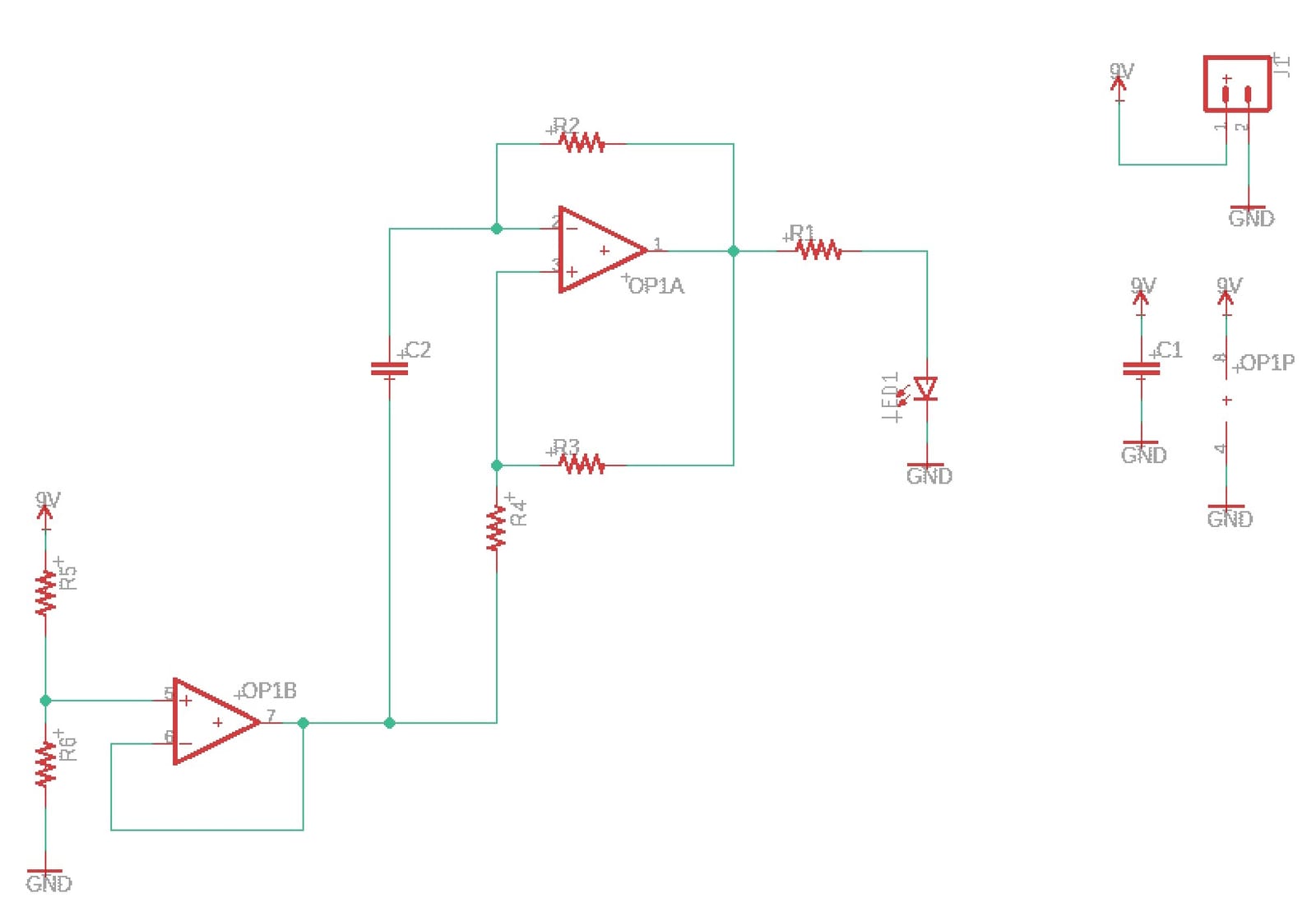
A schematic of the Blinky circuit: a dual op-amp labelled OP1A and OP1B with feedback resistors R2, R3, R4, a capacitor C2, a bias divider R5/R6, an output resistor R1 driving an LED to ground, and a 9-volt supply with a decoupling capacitor C1.
The Blinky schematic — a two-stage op-amp oscillator driving the LED, captured before layout.
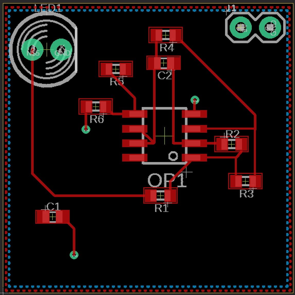
A PCB layout of the Blinky board: an 8-pin op-amp at centre, six surface-mount resistors and two capacitors placed around it, an LED footprint and a two-pin power connector, with red copper traces routing between them.
The same circuit as a routed board — every schematic net placed and traced by hand.

GoodNightLight: sensing the dark

The second circuit adds a sensor. A photocell and a fixed resistor form a voltage divider whose midpoint tracks ambient light; an op-amp comparator watches that midpoint against a reference and switches the LED on when the room goes dark — a night light with no switch.
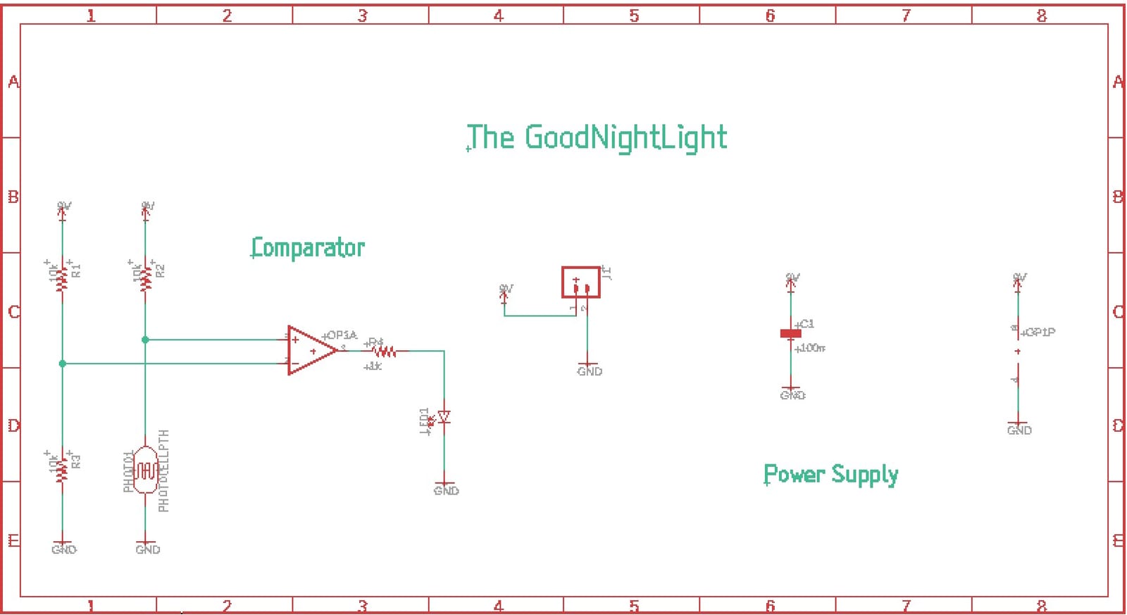
A schematic titled 'The GoodNightLight' with three sections labelled Comparator, power supply, and a connector. The comparator stage uses an op-amp OP1A with input resistors R1, R2, R3 and a photocell PHOTO1, driving an LED through R4; a 9-volt supply feeds a decoupling capacitor.
The GoodNightLight schematic: a photocell divider into an op-amp comparator that drives the LED when light falls below threshold.
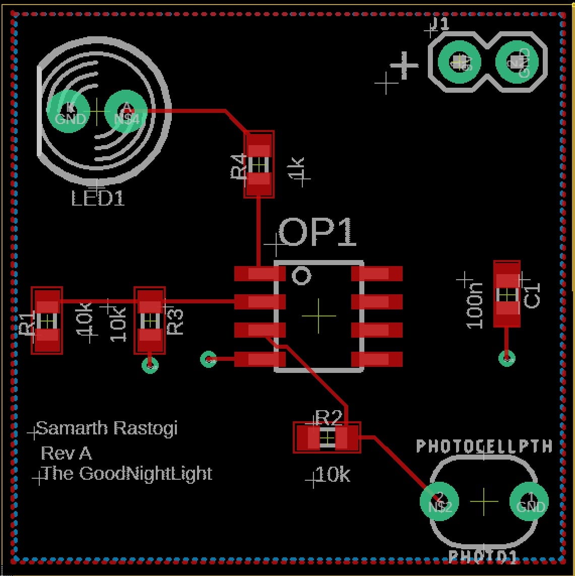
A PCB layout titled 'The GoodNightLight, Rev A, Samarth Rastogi' with an 8-pin op-amp at centre, surface-mount resistors R1 through R4, a 100 nF capacitor, an LED footprint, a photocell footprint labelled PHOTOCELLPTH, and a power connector, routed in red copper.
The GoodNightLight board, Rev A — photocell and comparator placed and routed for hand assembly.

Then the soldering: surface-mount resistors, the op-amp, the photocell, and a through-hole LED, all placed and reflowed by hand onto the fabricated board and powered from a 9 V battery.
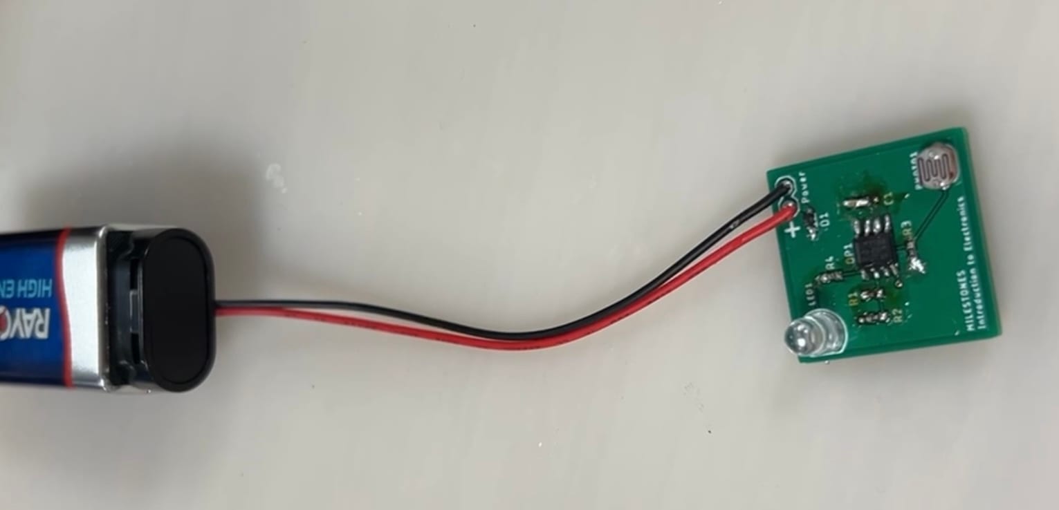
The finished green GoodNightLight PCB, hand-soldered with its op-amp, resistors, photocell, and LED, connected by red and black leads to a 9-volt battery, silkscreen reading 'MILESTONES Introduction to Electronics'.
The finished, soldered GoodNightLight running on a 9 V battery — schematic to working hardware, done end to end.

What it taught

The pair of circuits covers the whole electronics fundamentals loop: op-amp behaviour on a breadboard, schematic capture, PCB layout and routing, and surface-mount hand soldering — and, underneath all of it, the habit of proving a circuit works cheaply before spending a board on it. It’s the hands-on complement to the analog theory: the point where a comparator stops being a triangle on a page and becomes a light that comes on in the dark.
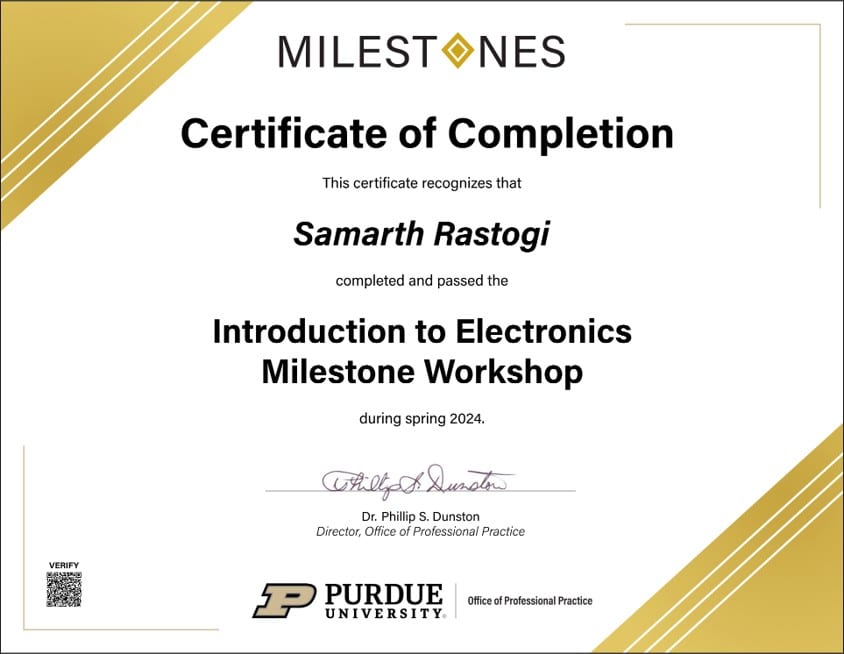
A Purdue University Milestones certificate of completion recognizing Samarth Rastogi for completing and passing the Introduction to Electronics Milestone Workshop during spring 2024, signed by the Director of the Office of Professional Practice.
The certificate — Introduction to Electronics Milestone Workshop, completed spring 2024.
Connected to
Technologies
EAGLE
Capabilities
Manufacturing
Organizations
Purdue University
Inspect the evidence2 items — click to open the archive
A small green printed circuit board, hand-soldered with surface-mount resistors, an 8-pin op-amp, a photocell, and a through-hole LED, powered by a 9-volt battery through red and black leads. The silkscreen reads 'MILESTONES Introduction to Electronics'.
photoAssembled GoodNightLight boardThe hand-soldered GoodNightLight, powered from a 9 V battery — the photocell-triggered light-in-the-dark circuit, laid out and built from scratch.
A Purdue University Milestones certificate of completion recognizing Samarth Rastogi for completing and passing the Introduction to Electronics Milestone Workshop during spring 2024, signed by the Director of the Office of Professional Practice.
photoIntroduction to Electronics — completion certificatePurdue Milestones: Introduction to Electronics Milestone Workshop, completed spring 2024.