Modular Workstation for Frontline Engineers

A folding work surface for the factory floor — 10 kg capacity at 2 kg unit weight, deployed one-handed in under four seconds.

Role Design team member
Team 4 people
Year Purdue, Fall 2023
Read the case study ↓
5:1load-to-weight ratio (10 kg capacity at 2 kg unit weight)measured
<4 ssingle-handed deployment timemeasured

The problem

On a factory floor there’s often nowhere to set a laptop down. Engineers doing co-ops and internships end up working standing over a machine, balancing a laptop on whatever’s flat, or not having a surface at all. Market research with interns confirmed it wasn’t a personal complaint but a widespread gap, and that’s what the project set out to close: a work surface that mounts to the structure already on the floor and folds away when it isn’t needed.

Requirements before geometry

The requirements came from the users, not from us. Scoping interviews with interns fixed the targets that then drove every design choice: it had to hold real weight, weigh little enough to mount and stow by hand, deploy fast and one-handed, and attach to the mix of Unistrut, aluminium extrusion, and beams that industrial environments are actually built from.

Those targets became numbers. The prototype carries 10 kg at a 2 kg unit weight — a 5:1 load-to-weight ratio — and folds out one-handed in under four seconds.
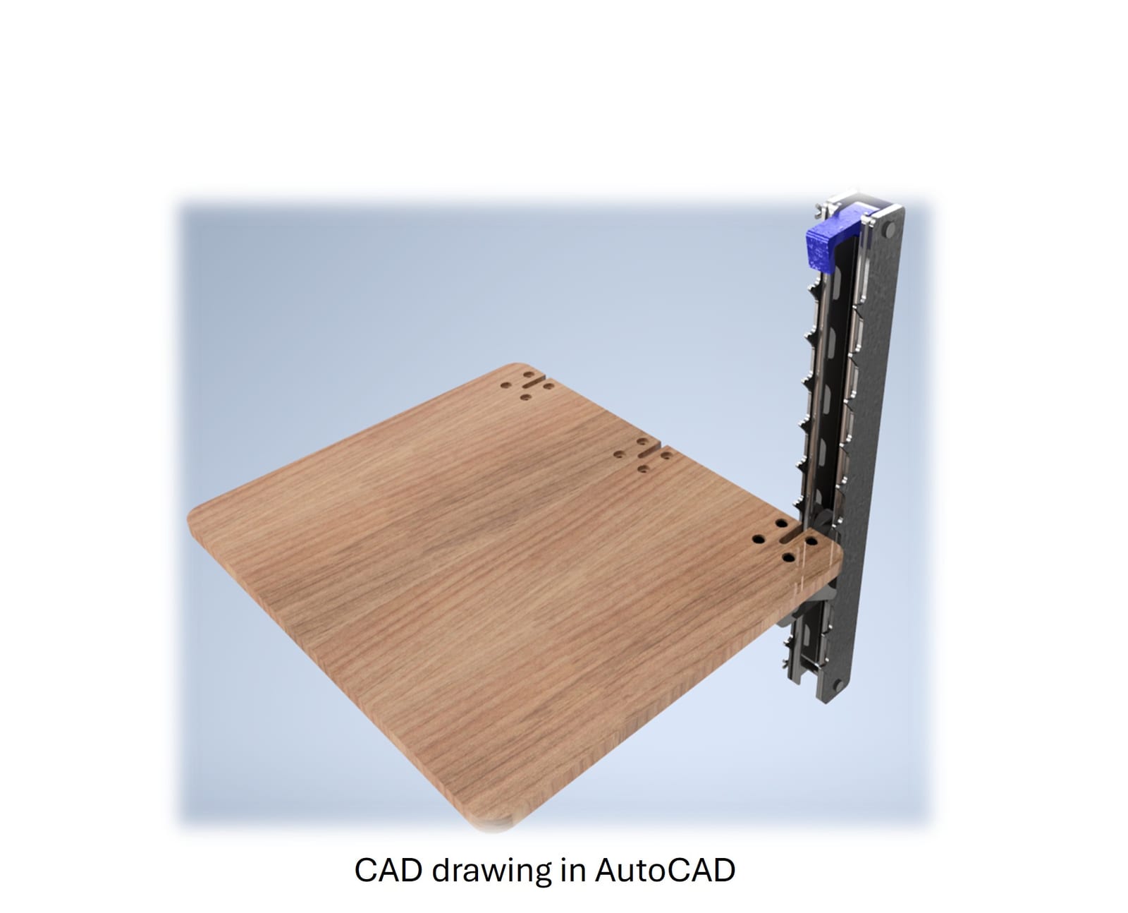
A SolidWorks render of the deployable workstation: a wood-grain rectangular work surface hinged to a black Unistrut channel and hook-sheet mount with a blue plastic latch at the top, floating on a pale blue gradient background.
The SolidWorks assembly: a work surface hinged off a Unistrut channel, hook sheets setting the height, and a latch to fold it flat when idle.

How it works

The mount is a length of Unistrut channel that fastens to whatever structural element is nearby. Two hook sheets ride the channel, letting the surface be pinned at different heights for standing or sitting; a machined carriage carries the hinge and the load into the channel; and a latch holds the surface folded up against the channel when it’s out of use, so it doesn’t eat floor space.
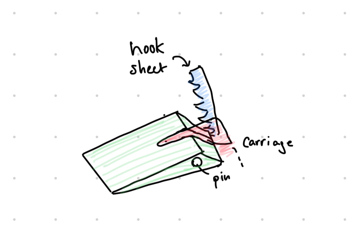
A hand sketch labelling the three interlocking parts of the mount: a blue hook sheet that slots into the channel, a red carriage that carries the surface, and the pin that joins them.
The mechanism in one sketch: the hook sheet sets the height, the carriage carries the surface, and a pin ties them together.
A looping CAD animation of the workstation folding down from its stowed vertical position against the channel to a deployed horizontal work surface.
The deploy motion in CAD: stowed flat against the channel, then folded out to a level surface — the sub-four-second one-handed action.

The carriage is where the load actually goes, so it was the part that got the analysis. A free-body diagram of the carriage — distributed load across the surface, reactions at the pin and the hook — sized the bracket and its joints before anything was machined.
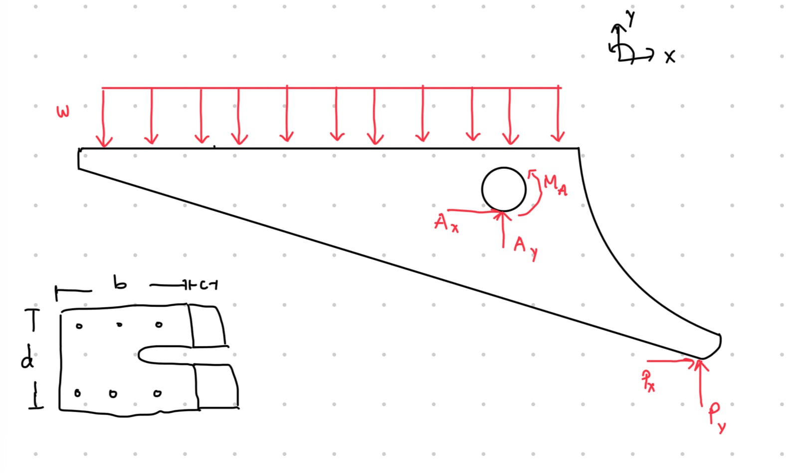
A hand-drawn free-body diagram of the carriage: a distributed load w across the top, a pin reaction with horizontal and vertical components and a moment at one support, and a second reaction at the far end, with the equilibrium equations for sum of forces and moments written below.
The carriage free-body diagram: distributed load across the surface, pin and hook reactions, solved for the loads the bracket and its joints had to carry.
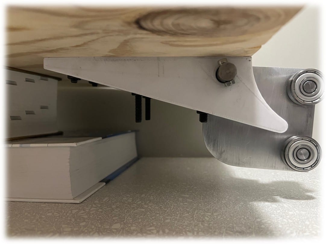
A close-up from underneath the deployed workstation showing a machined aluminium carriage bracket with two ball bearings on the right, bolts hanging through the plywood surface, and a thick book used to prop the assembly for the photo.
The machined carriage from underneath: the aluminium bracket, its bearings, and the bolted hinge that take the load into the channel.

Building it

The team iterated four design generations toward the reliability targets, then built and demonstrated a medium-fidelity prototype — machining the carriage and mount hardware and assembling it into a working unit.
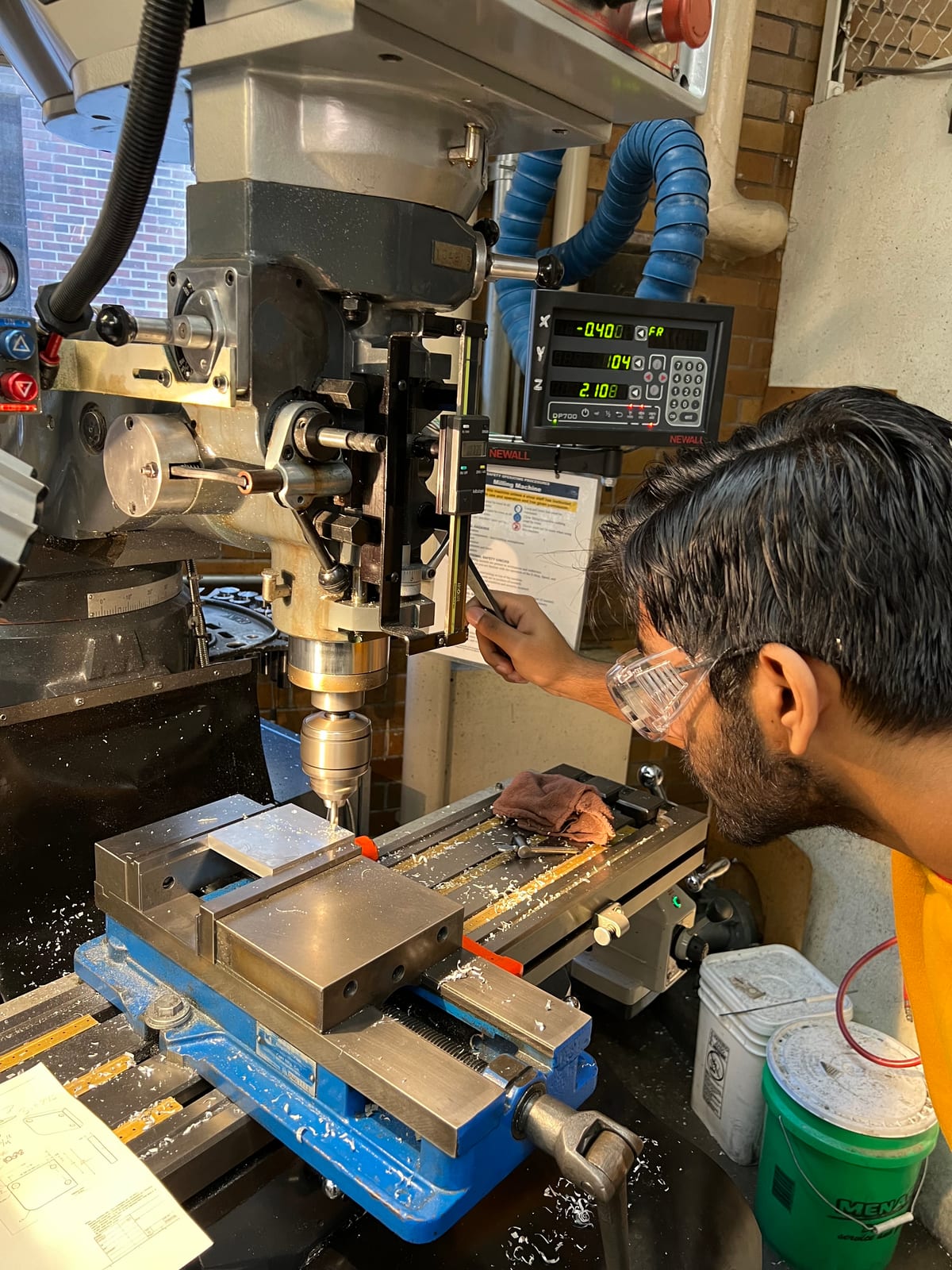
A person in safety glasses working at a manual milling machine with a digital readout, machining a metal part held in a blue vise, aluminium chips on the machine bed.
Machining the carriage hardware on a manual mill — the design leaving CAD for metal.
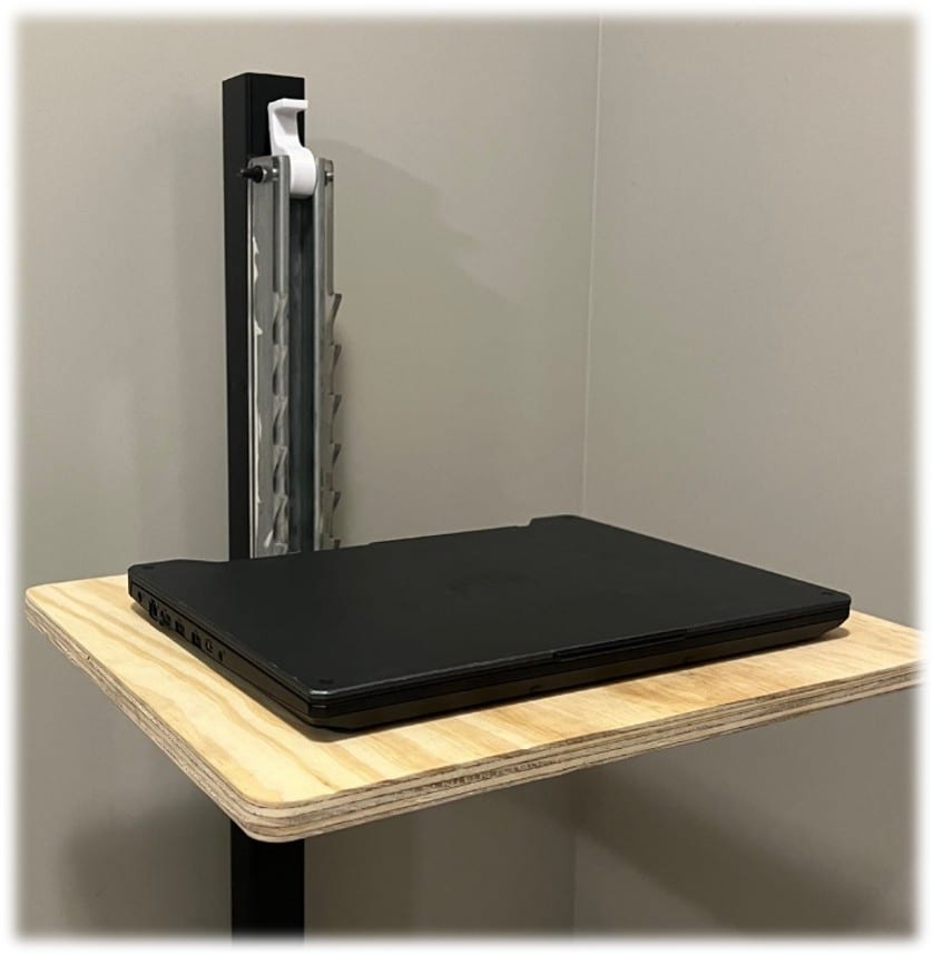
A prototype folding workstation clamped to a vertical black column against a wall, its plywood work surface extended horizontally with a laptop resting on it, a machined steel carriage and hinge visible where the surface meets the column.
The prototype mounted and deployed, holding a laptop — the requirement that started the project, met in hardware.

Outcome

The prototype met its load, weight, and deployment targets and demonstrated the core idea: a surface that clamps to the structure already on the floor and disappears when idle. My role was on the design team, contributing to the mechanism and the build. The lesson that carried forward is that the requirements were the design — the 5:1 ratio and the four-second deploy came straight out of the interviews, and hitting them was mostly a matter of not losing sight of numbers the users had already handed us.
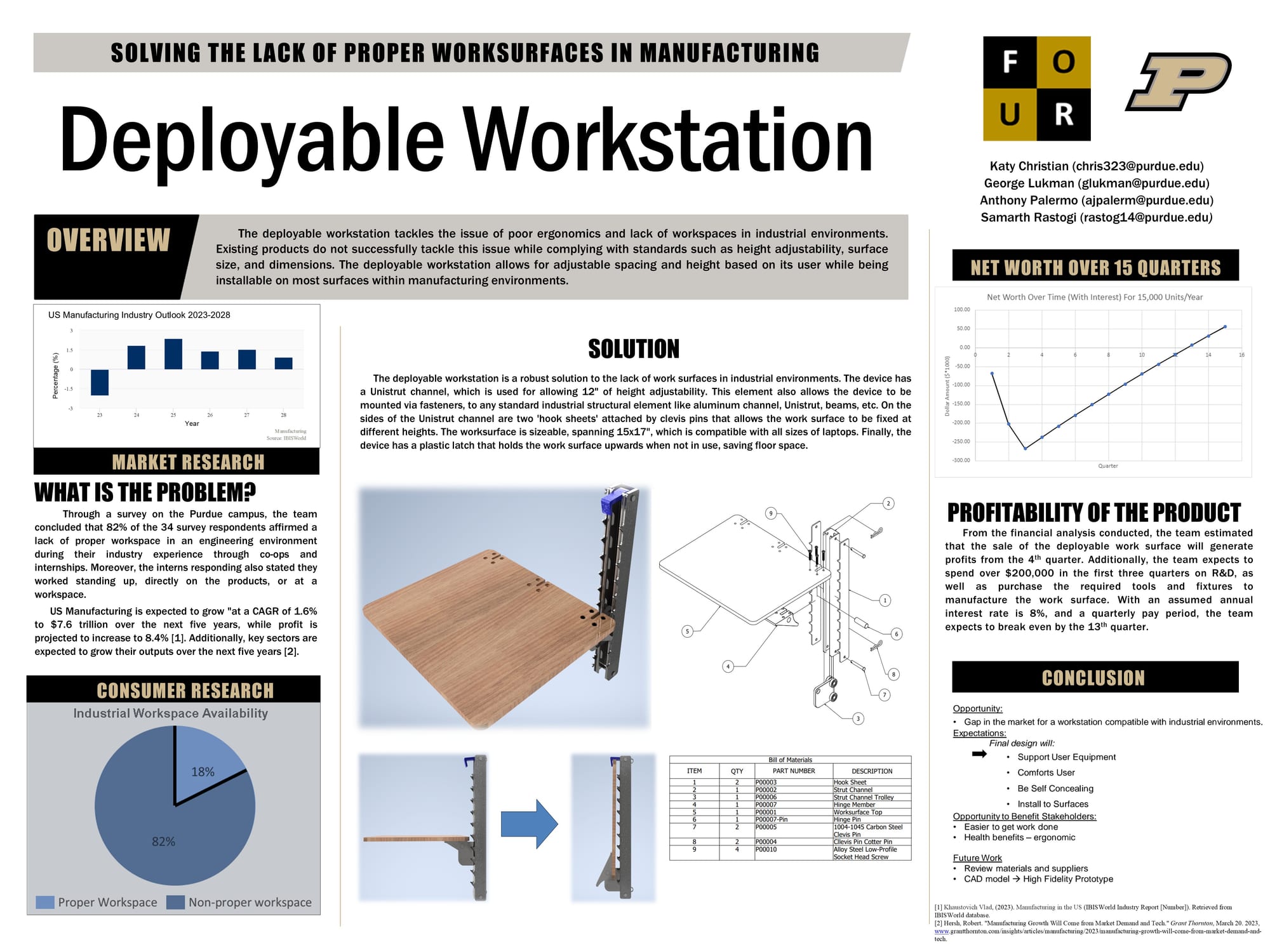
The team's design poster titled 'Deployable Workstation — Solving the Lack of Proper Worksurfaces in Manufacturing', with sections on market research, the CAD solution and bill of materials, a financial net-worth chart, and conclusions, carrying the Purdue and team logos.
The project poster: problem, market research, the CAD solution and bill of materials, and the business case behind the deployable workstation.
Connected to
Technologies
SOLIDWORKS
Capabilities
Mechanical Design · Rapid Prototyping
Organizations
Purdue University
Inspect the evidence3 items — click to open the archive
A SolidWorks render of the deployable workstation: a wood-grain rectangular work surface hinged to a black Unistrut channel and hook-sheet mount with a blue plastic latch at the top, floating on a pale blue gradient background.
cadDeployable workstation CADThe SolidWorks assembly: work surface, Unistrut channel, hook sheets, and the latch that folds it up when idle.
A prototype folding workstation clamped to a vertical black column against a wall, its plywood work surface extended horizontally with a laptop resting on it, a machined steel carriage and hinge visible where the surface meets the column.
photoPrototype workstation, deployedThe medium-fidelity prototype mounted and deployed, holding a laptop on its folded-out surface.
A close-up from underneath the deployed workstation showing a machined aluminium carriage bracket with two ball bearings on the right, bolts hanging through the plywood surface, and a thick book used to prop the assembly for the photo.
photoMachined carriage undersideThe machined carriage that rides the channel — bearings, hinge, and bolted joint that carry the load.