ThermOcean

A desalination platform driven primarily by the ocean's temperature gradient, with a solar-thermal boost in the full-scale design. Treating water cost as an energy problem cut it 51%.

Role Team Lead
Team 20 researchers
Year 2025–26
Read the case study ↓
BestBuild & Test honors — DOE Marine Energy Collegiate Competition, 27 teamsawarded
51%reduction in levelized water cost vs. the Gizo, Solomon Islands baselinemodeled
28,600liters of freshwater per day (modeled) — enough for 1,430 peoplemodeled
$21,000staged competition funding securedawarded
At a glance
Problem Desalination in Gizo is constrained by the cost of imported energy.
My contribution Led the 20-person team and designed the modular finned membrane-distillation channel, then built and led its test program.
Result The finned prototype produced roughly 2.5× the permeate of the unfinned baseline; the full-scale model projected 28,600 L/day at 51% lower water cost.
Evidence Side-by-side fin testing, the assembled prototype, full-scale design records, and DOE Best Build & Test honors.

The problem

Gizo, in the Solomon Islands, is the kind of place desalination was supposed to help: surrounded by seawater, short on fresh water, and at the end of a fuel supply chain that makes every liter expensive. Conventional desalination needs either grid electricity or active heating — and the cost of water there is, mostly, the cost of that energy.

The DOE Marine Energy Collegiate Competition asks teams to put marine energy to work on real coastal problems. We chose to make water.

The reframe

The cost problem was really an energy problem — so the thermocline did the work twice.

The ocean already maintains a temperature gradient — warm at the surface, cold below the thermocline. That gradient is low-grade energy, unusable for most machines but exactly the kind of heat a membrane-distillation process wants. The platform uses that gradient as its primary energy source: warm surface water drives evaporation across the membrane, while cold deep water pulls condensation. In the full-scale design, a solar collector raises the warm-side temperature to boost output. The concept needs no grid connection or fuel deliveries, so the energy bill — the thing that actually sets the price of water in Gizo — falls out of the design.

Simplified system diagram: cold deep water and warm surface water feed an energy cycle that drives a desalination unit producing fresh water, with a solar collector at the surface.
The system in one frame: warm surface water in red, cold deep water in blue, and the gradient between them doing the work.

Modeled output: 28,600 liters per day, fresh water for 1,430 people, with the projected levelized cost of water 51% below the Gizo baseline.
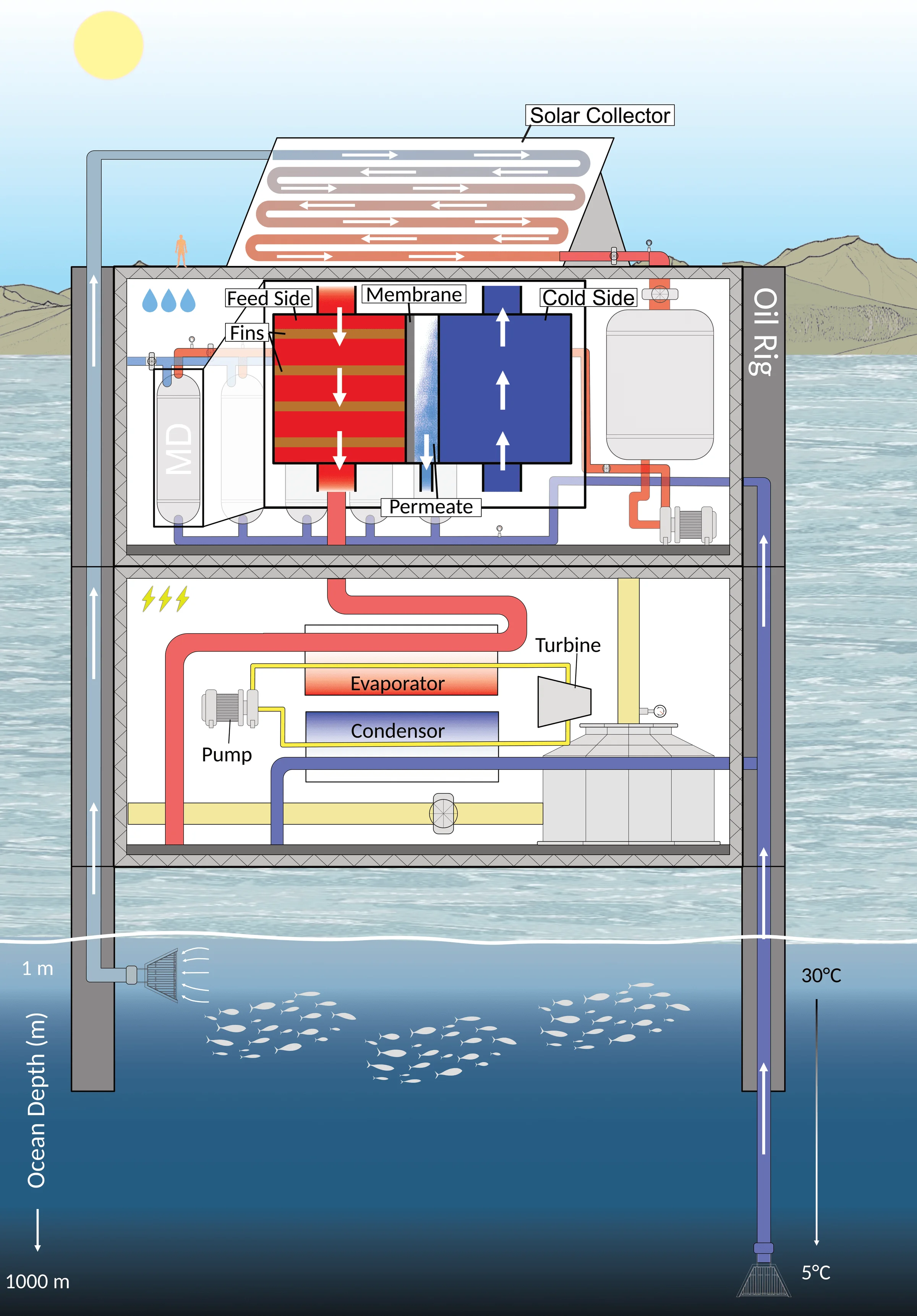
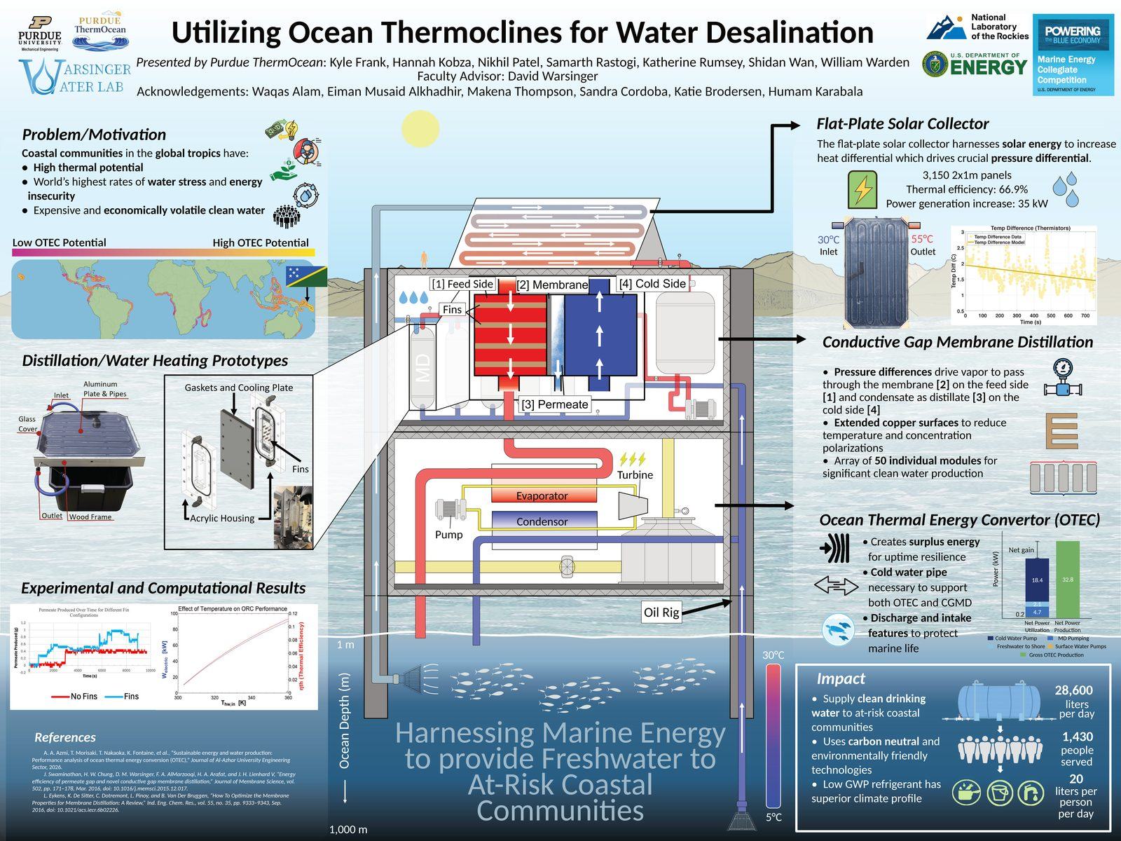
Cross-section of the full-scale platform on oil-rig legs: solar collector on top, membrane distillation deck and organic Rankine cycle deck below, with a cold-water pipe reaching 1,000 m and a 30 °C surface intake.
The full-scale architecture: solar collector on top, MD deck and power deck below, drawing 5 °C water from 1,000 m depth.

Design

The heart of the platform is a conductive-gap membrane-distillation module. My design contribution was its finned channel: a modular geometry that supports interchangeable fin configurations, so the team could test heat-transfer trade-offs in hardware instead of arguing about them in simulation.
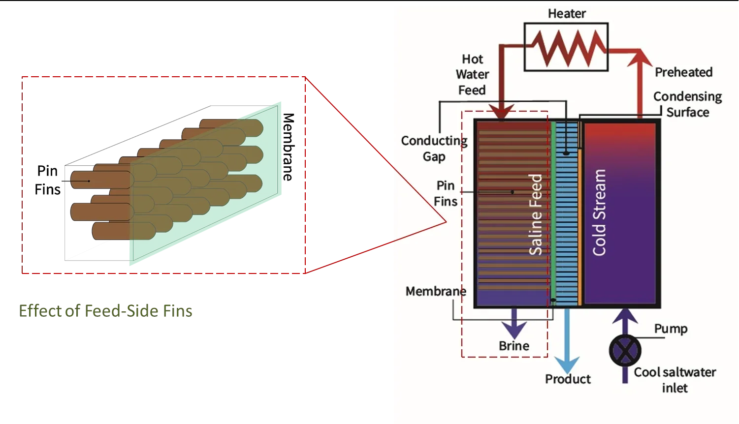
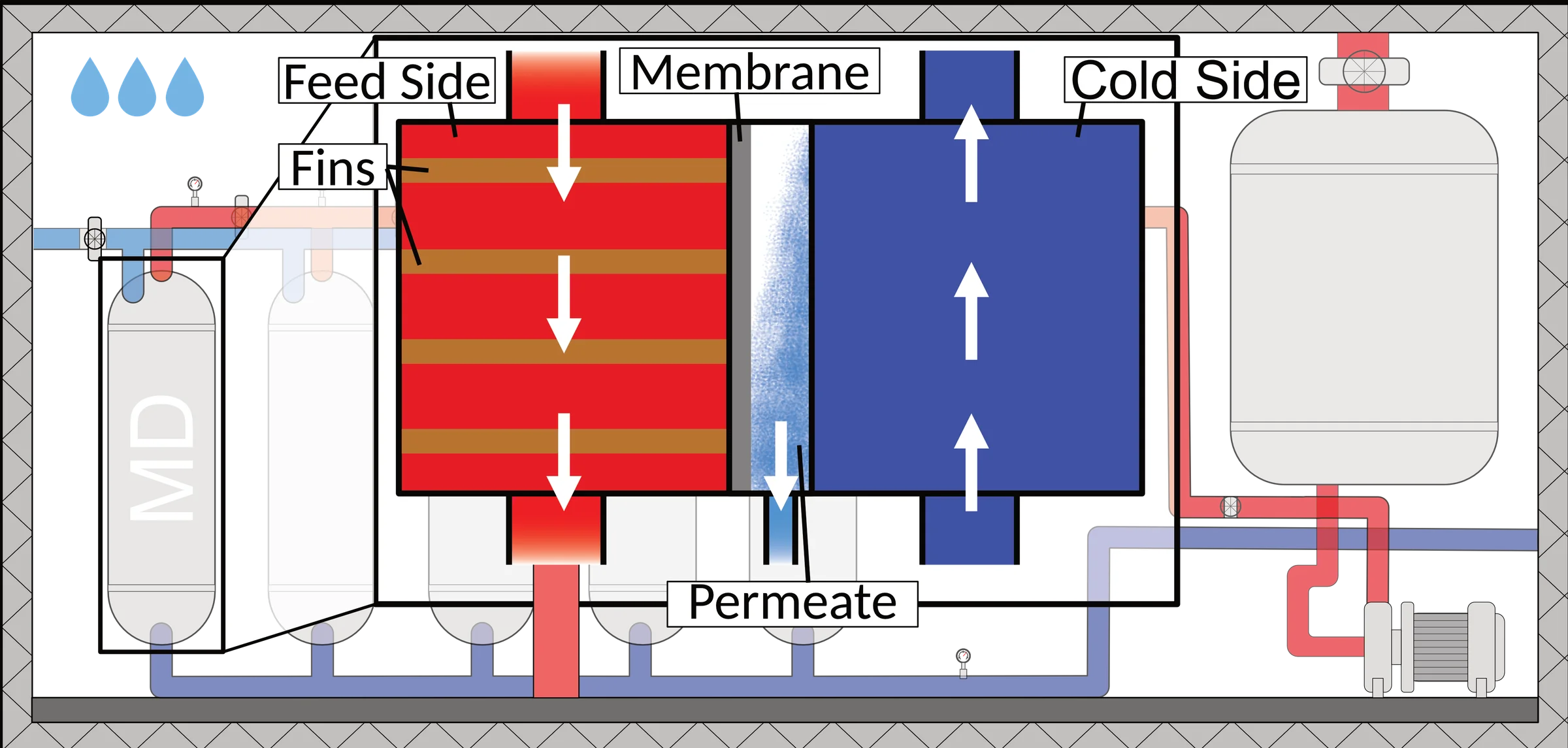
Diagram showing pin fins inside the conductive-gap membrane distillation module: a 3D cutaway of the fin array on the left, and a schematic cross-section on the right showing hot water feed through the fin side, membrane, conducting gap, and cold stream with pump.
How the fins work: pin fins on the hot feed side enhance flow mixing, reduce boundary-layer thickness, and increase heat and mass transfer across the membrane.
Cutaway of the membrane distillation deck: a finned hot feed side and a cold side across a membrane with a permeate channel, shown as one module of a five-vessel array.
The MD module in section — hot finned feed side, membrane, cold side. The finned channel is the design contribution the prototype went on to test.
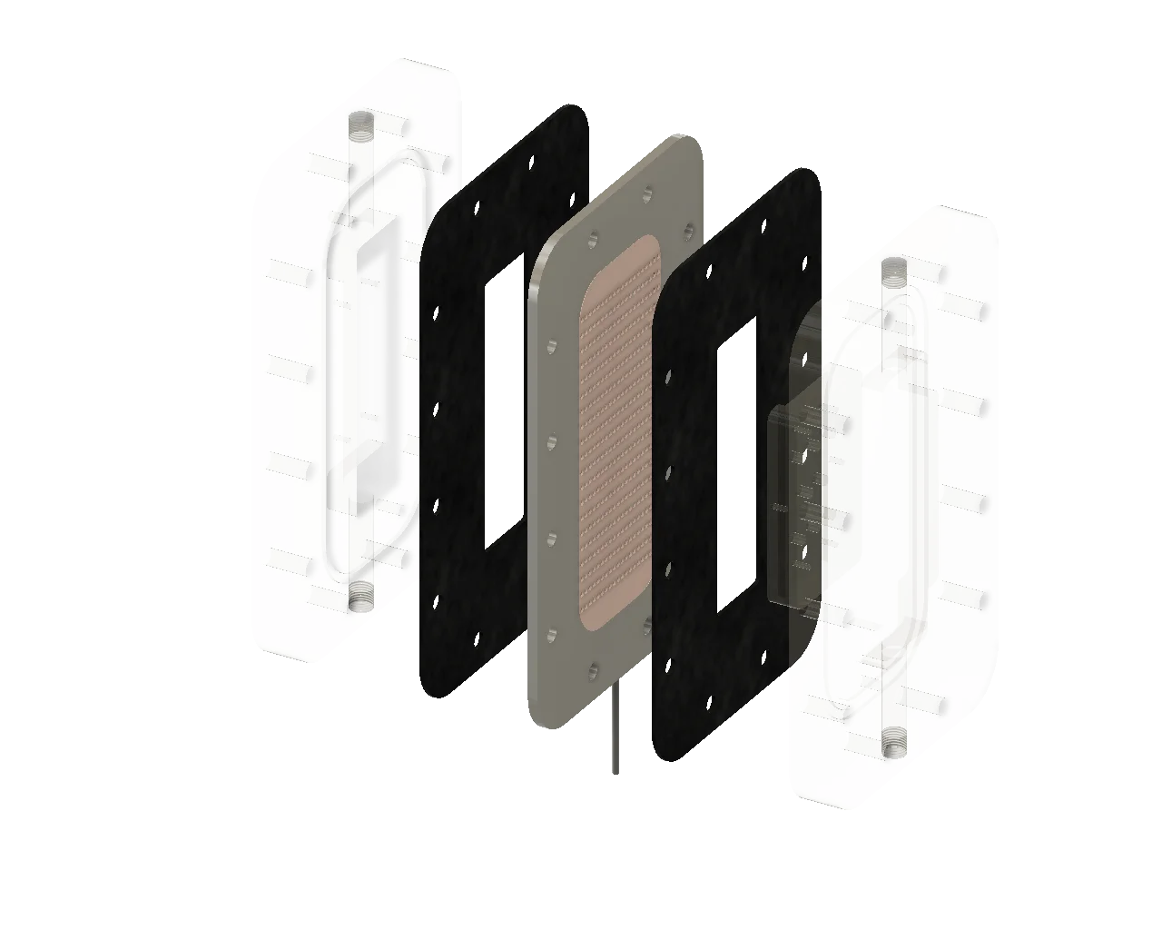
Exploded CAD render of the conductive-gap membrane distillation module: acrylic housings, gaskets, and the finned heat-transfer plate.Feed housingGasketFinned plateMembraneGasketCold housing
The as-built lab module, exploded: an interchangeable finned plate between gasketed acrylic housings.

Interchangeable fins turned a design argument into a test matrix. When the geometry is swappable, you don’t have to be right the first time — you have to be measurable.
The interchangeable finned plate, straight from the Fusion 360 assembly — drag to inspect the fin geometry the test matrix was built around.
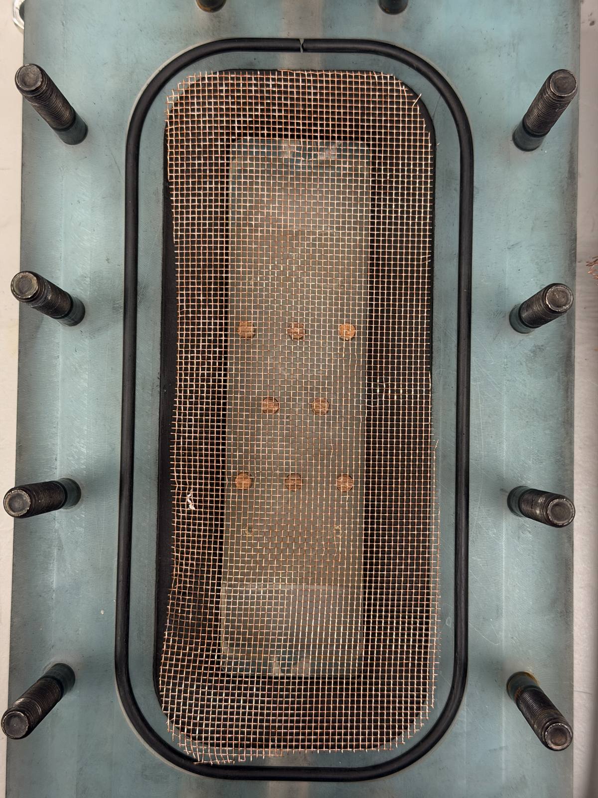
Close-up of the machined feed-side channel with the conductive pin fins installed, copper contacts soldered to the mesh.
The design in metal: feed-side fins as machined, before the module closed up for testing.

Full-scale, 50 of these modules run in parallel — 1,250 m² of active membrane area producing 5.55 LMH at a gained output ratio of 1.80.

Build & test

We built the lab-scale prototype and I led its testing. That end of the project — machining, sealing, instrumenting, running — is where the design either holds up or doesn’t.

Overhead photo of a cardboard system mockup with labeled turbine, generator, condenser, evaporator, pumps, water tank, and membrane distillation system connected by hoses.
Before any metal was cut: a full-system cardboard mockup that fixed the order of every piping connection — and killed the idea of building the Rankine cycle.
Handwritten stress analysis of the acrylic MD housing: bolt loads and plate bending at 500 kPa, giving factors of safety of 217 for the bolts and 3,579 for the acrylic channel.
The hand calcs behind the acrylic housing: bolt and plate stresses at 500 kPa, factors of safety established before machining.
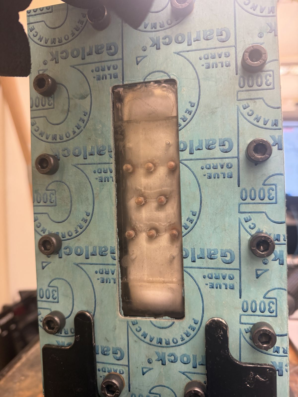
Close-up photograph of the assembled conductive-gap membrane distillation module: copper mesh visible through the machined acrylic channel, sealed with a Garlock Blue-Gard gasket and bolted together.
The assembled module: copper mesh through acrylic, Garlock gasket, bolted housing. Every connection on this thing leaked at least once.

The modular sandwich architecture — acrylic housings, gaskets, membrane, finned plate — meant the module was repeatedly assembled, tested, disassembled, and reassembled with different fin configurations. That flexibility was the point of the design, but it made sealing a transient problem. The initial plastic swivel joints ruptured under pressure, sending us back to research better fittings that could swivel and still hold. The food-grade replacements leaked too — five hours of in-lab troubleshooting before we found a joint configuration that sealed reliably through repeated coupling cycles.

The modular architecture was the right call, but modularity taxes every seal. Five hours of chasing leaks through swivel joints taught us that the connection is the design, not the thing it connects.
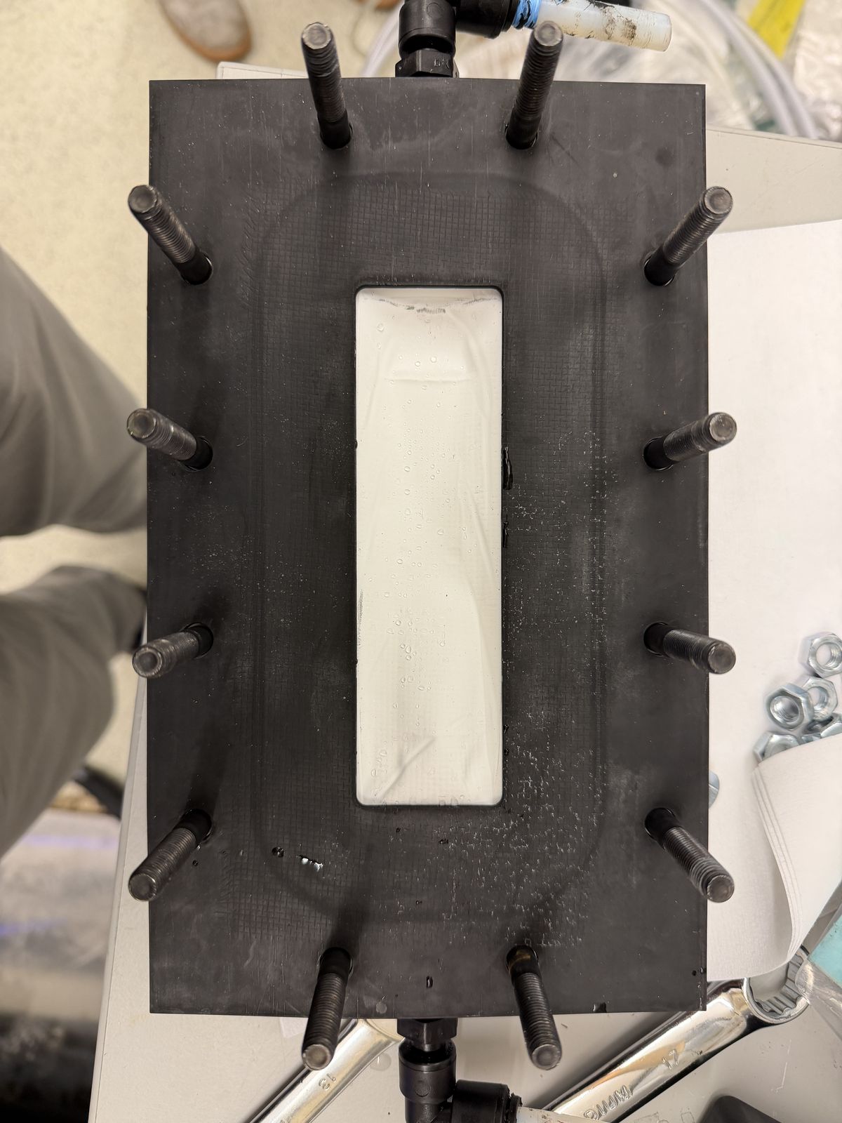
The gasket and housing stack partially assembled, condensation visible on the membrane surface before closing.
The sandwich mid-assembly — every one of these interfaces is a seal that has to survive repeated opening.

A CNC error on one housing left a feature shallower than spec. Rather than re-machine, we iterated on the gasket stack — adjusting thicknesses until the existing housing sealed at pressure. That kind of recovery matters more than getting it right the first time.
Assembling the module: housing, gasket, mesh, membrane — the stack in real time.
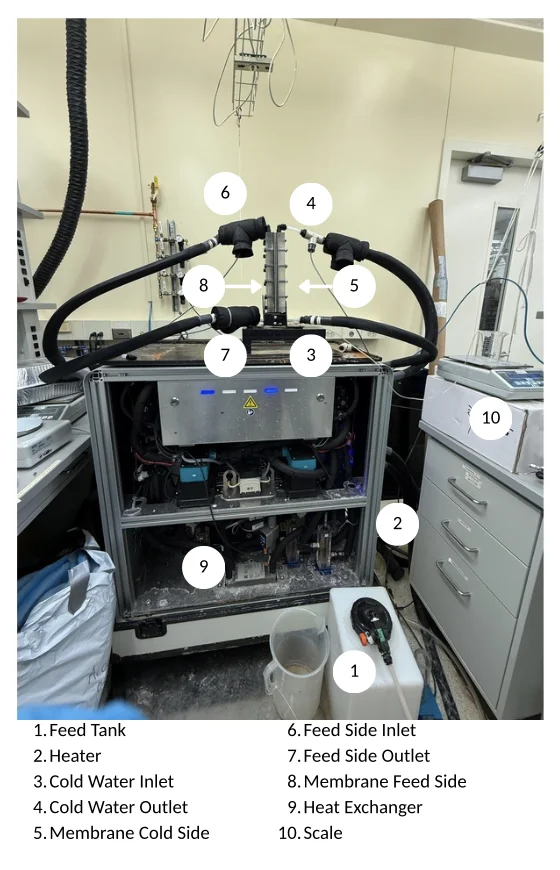
Annotated photograph of the membrane distillation test rig in the Warsinger Lab, with numbered labels identifying the feed tank, heater, cold water inlet and outlet, membrane feed and cold sides, feed side inlet and outlet, heat exchanger, and scale.
The test rig, labeled: feed tank, heater, cold- and hot-water loops through the membrane module, heat exchanger, and the scale that caught every gram of permeate.
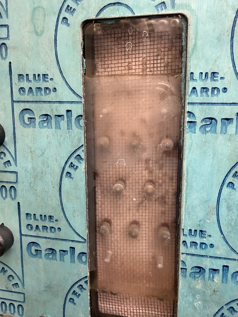
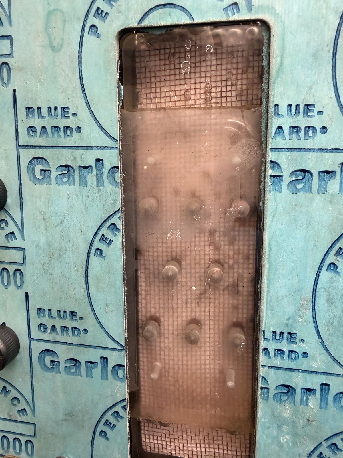
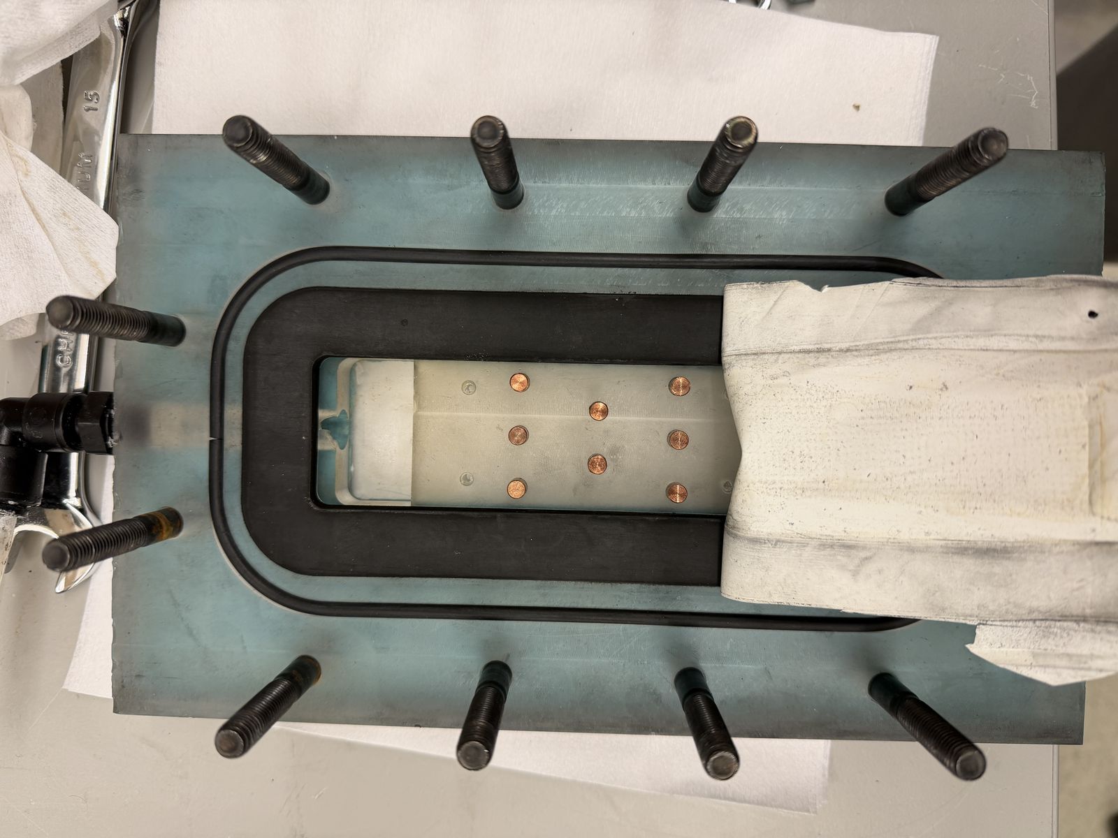
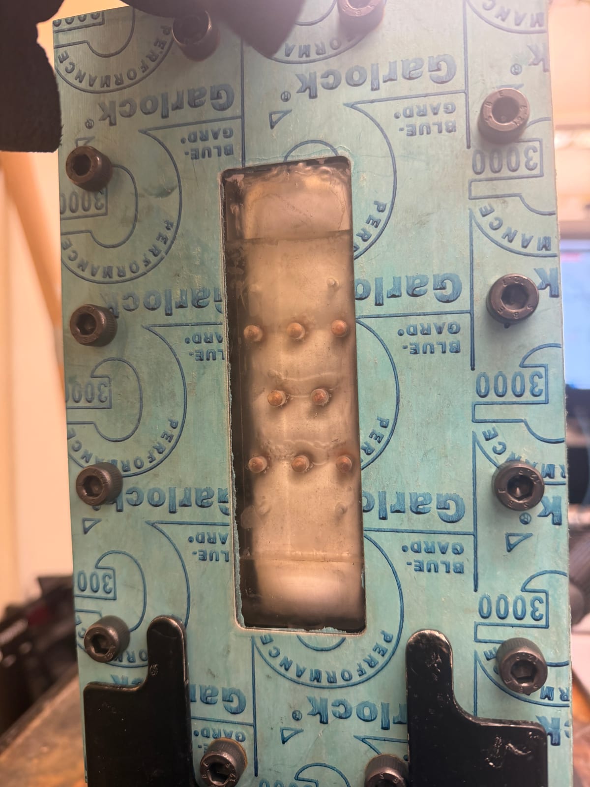
Top-down view of the assembled conductive-gap membrane distillation module during a test: a teal Garlock Blue-Gard gasket bolted around a rectangular window that exposes the membrane, with the pin-fin bumps and beads of permeate condensation visible through it.
The module mid-run: through the membrane window you can see the pin-fin impressions and permeate beading on the far side — the design doing exactly what it was built to do.

With sealing solved, we ran the comparison that the whole finned-channel design existed to make possible: fins versus no fins, same module, same conditions.
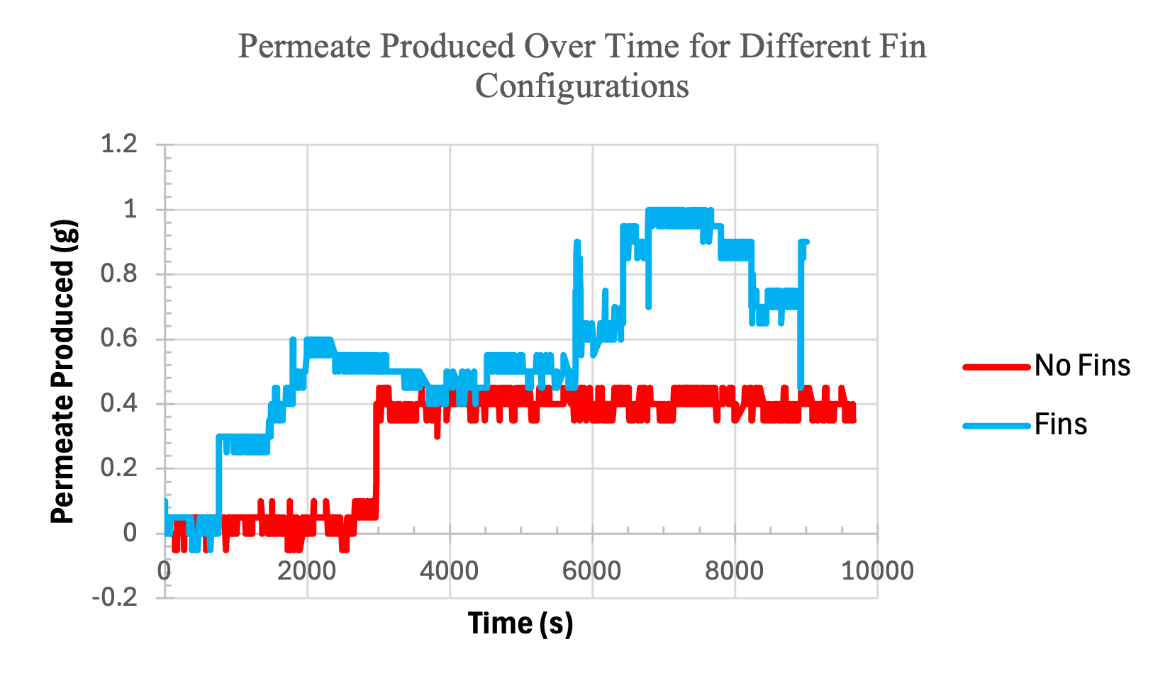
Line chart of permeate produced over time comparing finned and unfinned CGMD configurations: the finned module reaches roughly 1.0 g while the unfinned plateaus near 0.4 g, demonstrating approximately 2.5 times higher output with fins.
The test that justified the design: finned configuration produces roughly 2.5 times the permeate of the unfinned baseline under identical conditions.

The finned configuration produced roughly 2.5 times the permeate output of the unfinned baseline. The fins enhance flow mixing, thin the boundary layer, and increase both heat and mass transfer across the membrane — exactly the mechanism the design predicted, now measured.

It held up. The team won Best Build & Test honors against 27 teams at the DOE Marine Energy Collegiate Competition, a judgment specifically of prototype design and testing rigor.

Leading the team

Twenty undergraduate and graduate researchers, two DOE competitions running in parallel. I set MECC’s technical direction, drove the industry-mentor strategy, and aligned the Hydropower Collegiate Competition planning with its incoming lead. The budget — $21,000 in staged competition funding tied to proposal deliverables — I built and managed first, then deliberately delegated.

Beyond the engineering, I owned the business plan: site selection, stakeholder mapping, financial modeling, and the deployment roadmap we presented to DOE judges. Gizo wasn’t a default — it was selected from eight candidate sites in the Solomon Islands by overlaying bathymetric data with population density, existing water infrastructure, and proximity to the 1,000-meter depth contour the cold-water intake requires.
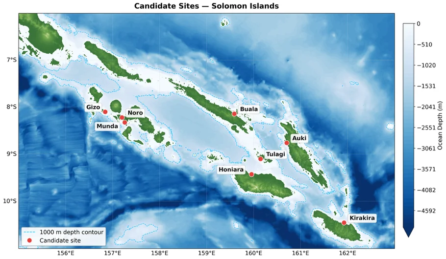
Bathymetric map of the Solomon Islands showing candidate deployment sites (Gizo, Munda, Noro, Buala, Auki, Tulagi, Honiara, Kirakira) marked with red dots, with a dashed cyan 1,000-meter depth contour indicating where cold deep water is accessible near shore.
Eight candidate sites scored against bathymetry, population, and water access — Gizo won because the 1,000 m contour runs close to shore.

The model we pitched: an Independent Water and Power Producer that sells freshwater to the community at below the next-best-alternative price, funded by impact investors who gain a tax break. No financial burden on the community; profits reinvested into scaling and research.
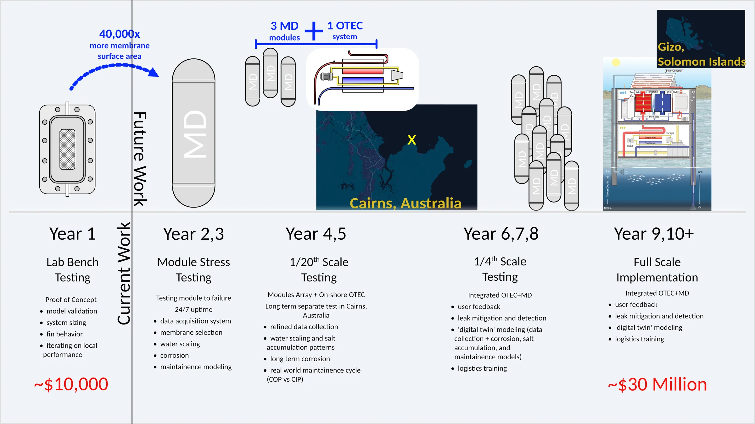
Timeline from year-one lab bench testing (~$10,000) through module stress testing and 1/20th- and 1/4-scale trials in Cairns, Australia, to full-scale deployment in Gizo, Solomon Islands (~$30 million).
The scaling case we argued to the DOE: lab bench to Gizo in ten years, $10k to $30M.

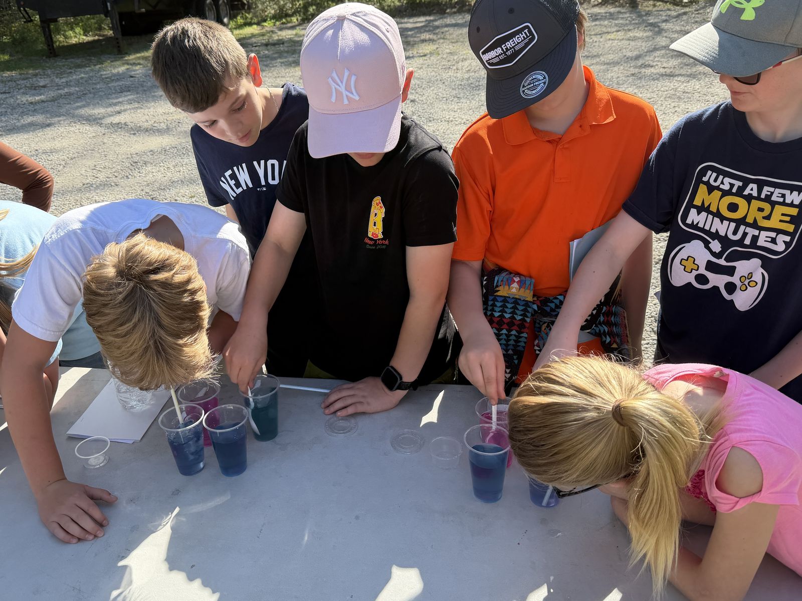
The work also traveled: we co-authored and presented “Utilizing Ocean Thermoclines for Water Desalination” at NCUR 2026, pitched at the OREC MECC conference in Portland, and ran three K-12 outreach events that put hands-on builds in front of 226 students.

Samarth pitching ThermOcean at a podium during the DOE MECC conference in Portland, 2026.
The quick pitch at MECC, Portland 2026 — the platform in ninety seconds.
K-12 students outdoors running a hands-on water-testing demonstration at a ThermOcean outreach event.
One of the three outreach events: 226 students total, hands on the same water problems the platform solves.

Lessons

The project’s central lesson is the reframe itself: the most expensive part of a system is often an energy flow wearing a cost costume. Finding the gradient that’s already there — and using it twice — beat every version of the design that tried to fight thermodynamics head-on.
Connected to
Technologies
SOLIDWORKS · ANSYS
Capabilities
Mechanical Design · Manufacturing · Systems Integration · Rapid Prototyping · Leadership
Organizations
Warsinger Water Lab · Purdue University · U.S. Department of Energy
Research areas
Marine Energy · Desalination · Thermal Systems
Inspect the evidence46 items — click to open the archive
Simplified system diagram: cold deep water and warm surface water feed an energy cycle that drives a desalination unit producing fresh water, with a solar collector at the surface.
diagramSystem concept — thermocline-driven desalinationThe one-slide version of the system: the ocean’s own temperature gradient drives both the energy cycle and the desalination.
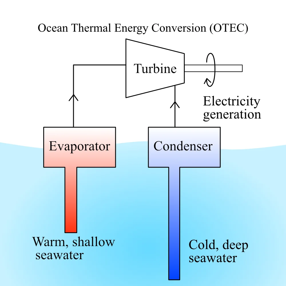
Schematic of Ocean Thermal Energy Conversion: warm shallow seawater feeds an evaporator and cold deep seawater a condenser, driving a turbine for electricity generation.
diagramConcept — OTEC cycle schematicBaseline OTEC cycle considered during concept generation.
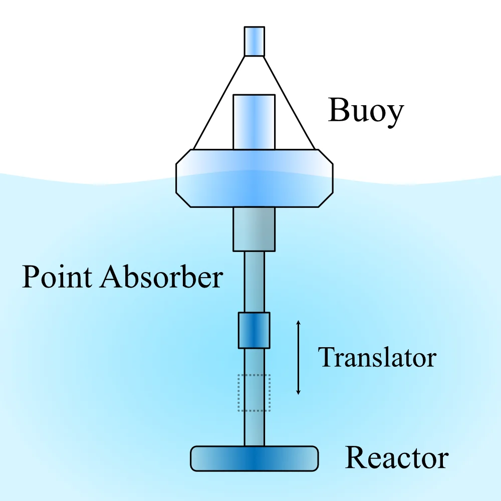
Diagram of a point absorber: a floating buoy drives a translator along a reactor shaft below the surface, converting wave motion to power.
diagramConcept — point-absorber wave energyWave-energy point absorber evaluated as an auxiliary power source.
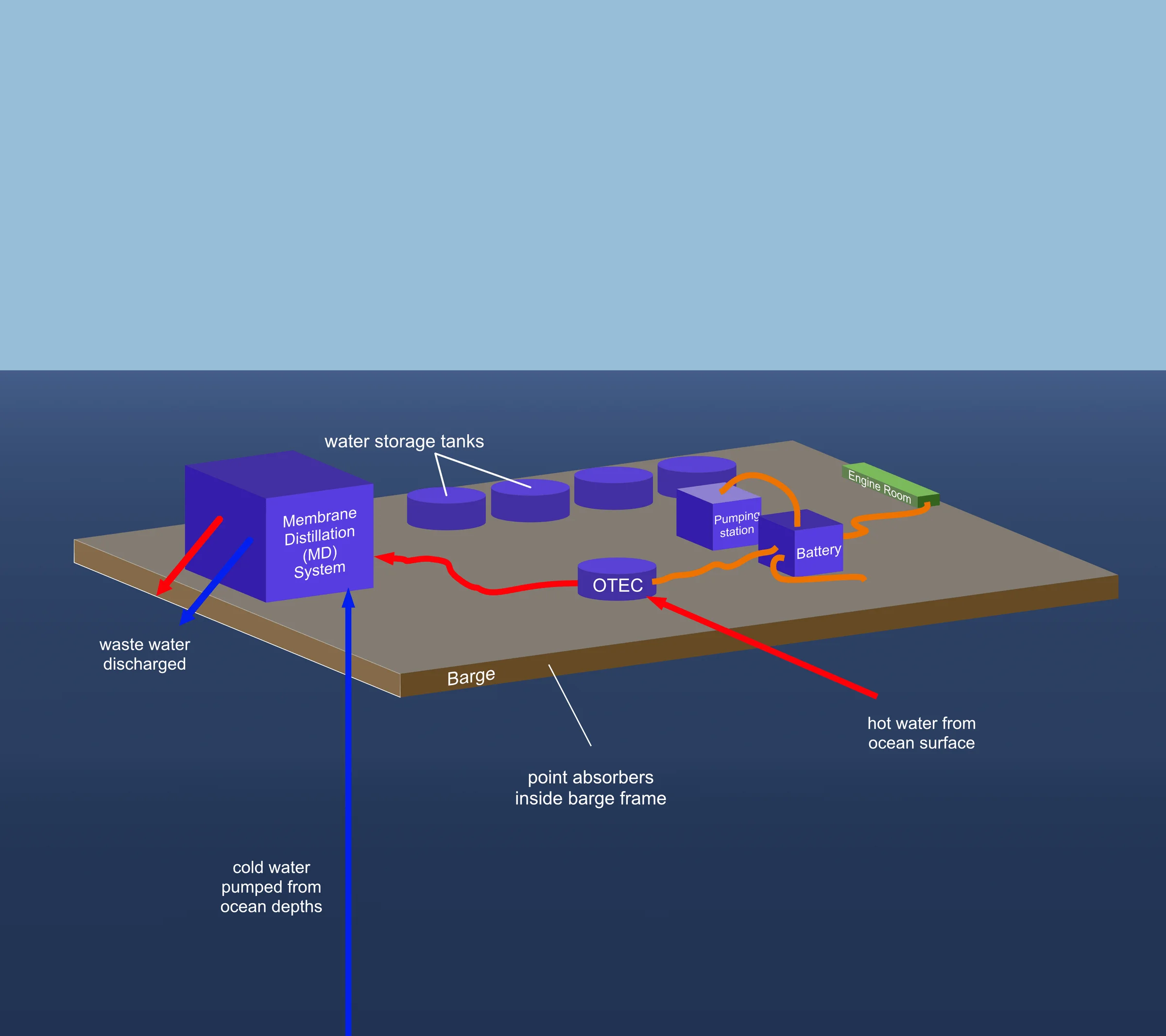
3D concept of a barge carrying the membrane distillation system, water storage tanks, OTEC unit, pumping station, battery, and engine room, with point absorbers inside the barge frame.
diagramConcept — offshore barge platformOffshore barge variant: everything on one hull, point absorbers built into the frame.
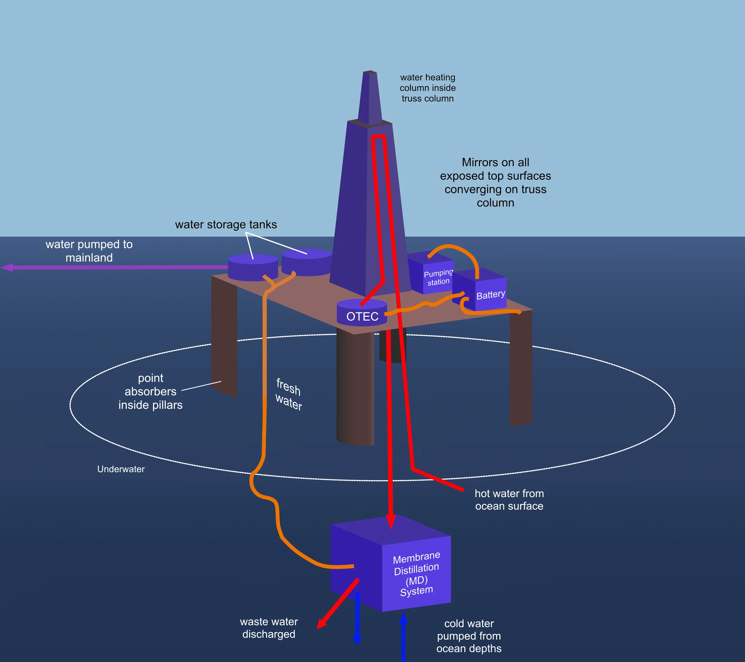
3D concept of a fixed offshore platform with a mirror-focused water-heating truss column, deck-mounted OTEC and storage tanks, a submerged membrane distillation unit, and fresh water pumped to the mainland.
diagramConcept — fixed offshore platformFixed-platform variant: solar-heated truss column, submerged MD unit, water piped ashore.
3D concept of an onshore desalination plant: shore-based membrane distillation and storage tanks fed by offshore point-absorber buoys, an OTEC unit, and a mirror-array solar water heater.
diagramConcept — onshore plantOnshore variant: seawater is pumped ashore, keeping all equipment on land.
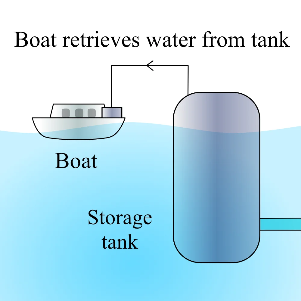
Sketch of a boat retrieving fresh water from a floating offshore storage tank.
diagramConcept — boat water retrievalWater logistics option: boats collect from an offshore storage tank.
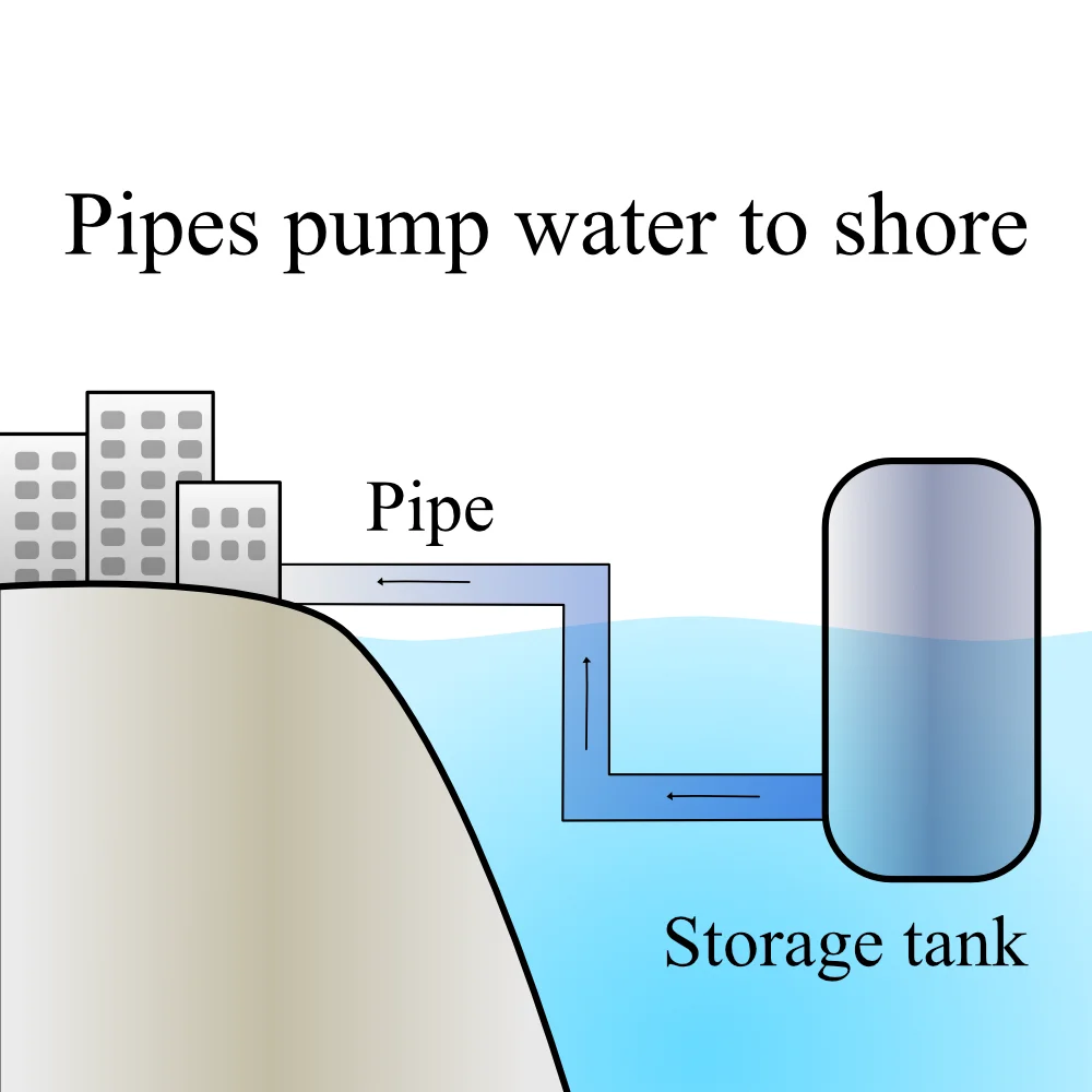
Sketch of a pipe pumping fresh water from an offshore storage tank to buildings on shore.
diagramConcept — piped delivery to shoreWater logistics option: a fixed pipe delivers water to shore.
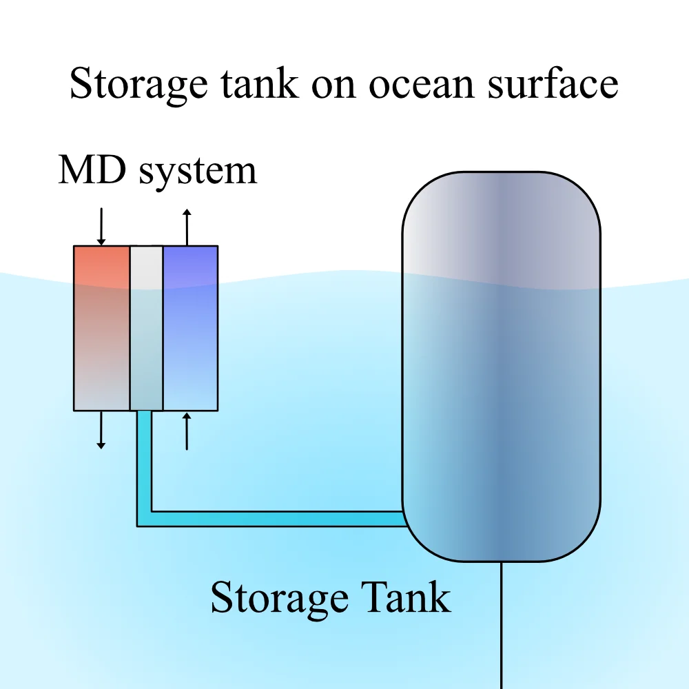
Sketch of a membrane distillation system feeding a storage tank floating at the ocean surface.
diagramConcept — surface storage tankStorage option: freshwater tank floating at the surface.
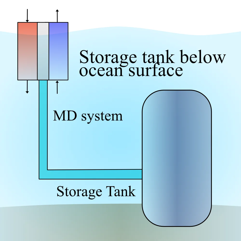
Sketch of a membrane distillation system feeding a storage tank anchored below the ocean surface.
diagramConcept — submerged storage tankStorage option: submerged tank, clear of surface traffic.
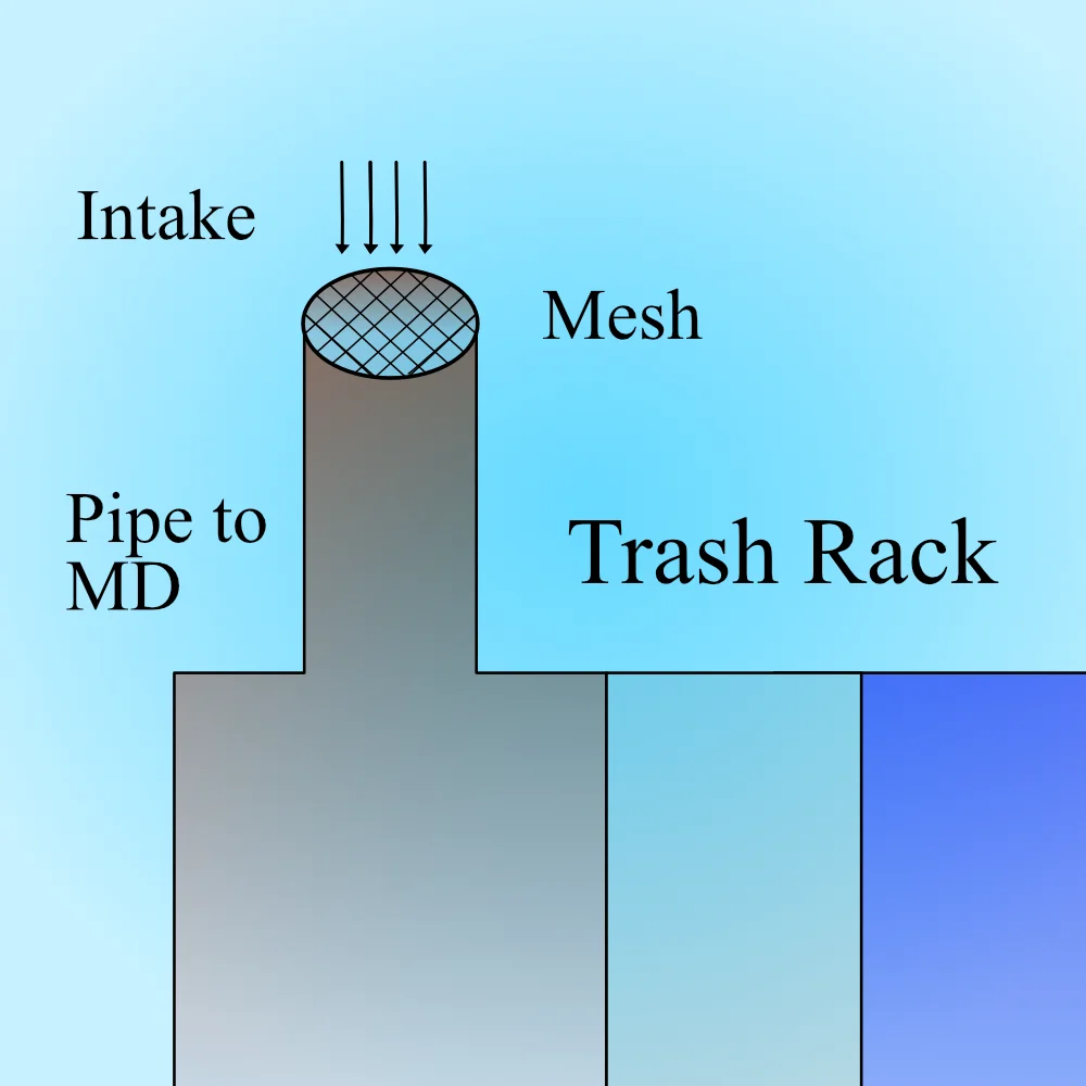
Sketch of a seawater intake protected by a mesh trash rack ahead of the pipe to the membrane distillation system.
diagramConcept — trash-rack intakeIntake protection: a mesh trash rack keeps debris out of the MD feed.
Sketch of silicone sealant applied between two bolted plates of an assembly.
diagramConcept — silicone sealingSealing approach carried into the prototype: silicone between bolted assemblies.
Overhead photo of a cardboard system mockup with labeled turbine, generator, condenser, evaporator, pumps, water tank, and membrane distillation system connected by hoses.
photoPrototype — annotated piping mockupFull-system cardboard mockup used to fix the order of piping connections before committing to hardware.
Slide titled Membrane Distillation and Organic Rankine Cycle System: a photo of the cardboard mockup beside bullets recording the decision to model but not build the ORC.
photoPrototype — MD and ORC system decisionsThe mockup’s output: piping order fixed, and the ORC judged too complex and expensive to build — modeled instead.
Cross-section of the full-scale platform on oil-rig legs: solar collector on top, membrane distillation deck and organic Rankine cycle deck below, with a cold-water pipe reaching 1,000 m and a 30°C surface intake.
diagramDesign — full-scale platform cross-sectionFull-scale architecture: MD deck above, power cycle below, drawing 5°C water from 1,000 m depth.
Cutaway of the membrane distillation deck: a finned hot feed side and a cold side across a membrane with a permeate channel, shown as one module of a five-vessel array.
diagramDesign — MD module sectionThe MD module in section — the finned feed channel is the design contribution the prototype tested.
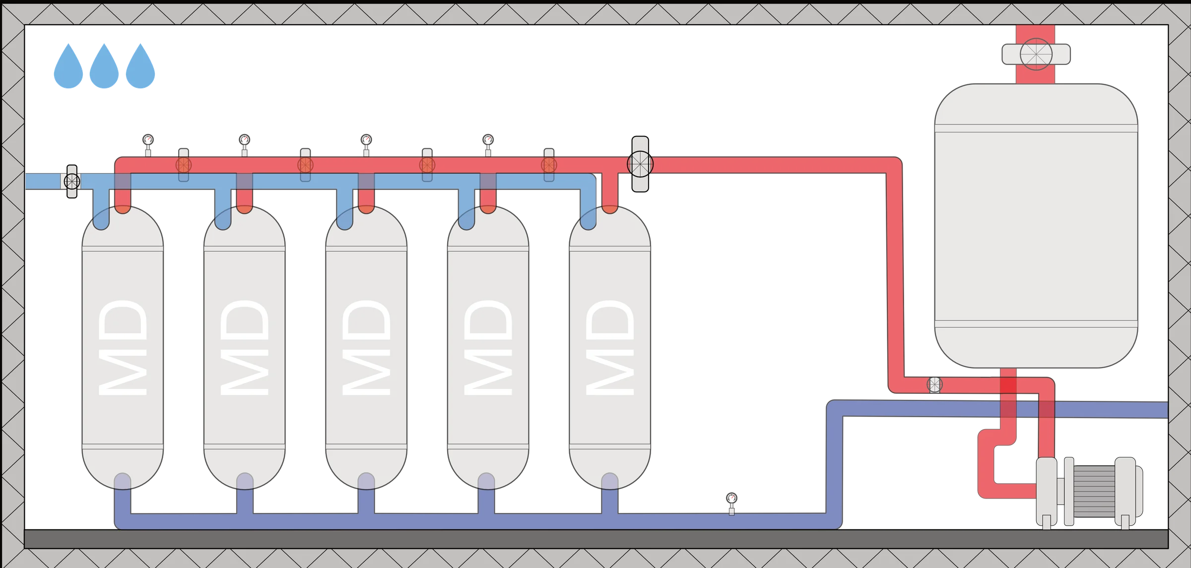
Piping diagram of five membrane distillation vessels manifolded in parallel between hot and cold lines, with a storage tank and pump.
diagramDesign — five-module MD arrayFive MD modules manifolded in parallel on the full-scale deck.
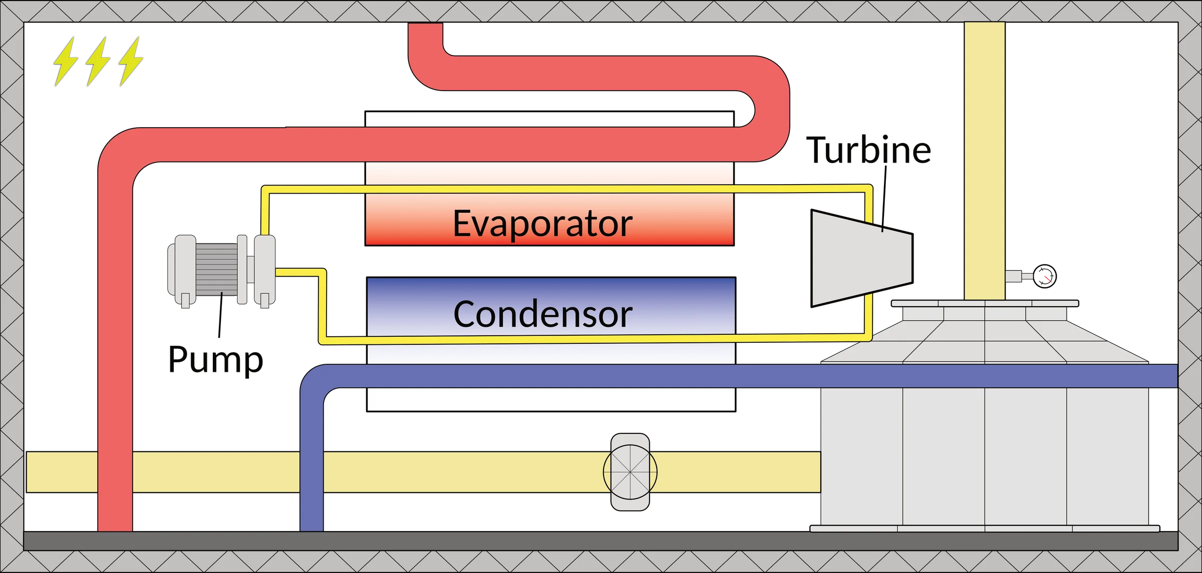
Diagram of the organic Rankine cycle deck: pump, evaporator, condenser, and turbine in a closed loop between hot and cold seawater lines.
diagramDesign — organic Rankine cycle sectionThe power deck: a closed Rankine loop spanning the same thermal gradient.
Diagram of a serpentine solar collector heating seawater across successive passes from a cool inlet to a hot outlet.
diagramDesign — solar collectorSolar boost: a serpentine collector raises feed temperature before the MD deck.
Diagram showing pin fins inside the conductive-gap membrane distillation module: a 3D cutaway of the fin array on the left, and a schematic cross-section on the right showing hot water feed through the fin side, membrane, conducting gap, and cold stream with pump.
diagramPin fin effect — CGMD flow schematicHow the pin fins work: a 3D cutaway of the fin array and a flow schematic of the conductive-gap membrane distillation module.
Exploded CAD render of the conductive-gap membrane distillation module: acrylic housings, gaskets, and the finned heat-transfer plate.
cadBuild — finned CGMD module, exploded CADThe as-built lab module: an interchangeable finned plate between gasketed acrylic housings.
Handwritten stress analysis of the acrylic MD housing: bolt loads and plate bending at 500 kPa, giving factors of safety of 217 for the bolts and 3,579 for the acrylic channel.
reportBuild — housing stress analysisHand calcs behind the housing: bolt and plate stresses at 500 kPa, factors of safety before machining.
Close-up photograph of the assembled conductive-gap membrane distillation module: copper mesh visible through the machined acrylic channel, sealed with a Garlock Blue-Gard gasket and bolted together.
photoAssembled CGMD module — close-upThe assembled conductive-gap membrane distillation module: copper mesh through acrylic, Garlock gasket, bolted housing.
Timeline from year-one lab bench testing (~$10,000) through module stress testing and 1/20th- and 1/4-scale trials in Cairns, Australia, to full-scale deployment in Gizo, Solomon Islands (~$30 million).
diagramBusiness — ten-year scaling planThe scaling case: lab bench to Gizo in ten years, $10k to $30M.
Bathymetric map of the Solomon Islands showing candidate deployment sites (Gizo, Munda, Noro, Buala, Auki, Tulagi, Honiara, Kirakira) marked with red dots, with a dashed cyan 1,000-meter depth contour indicating where cold deep water is accessible near shore.
diagramSite selection — Solomon Islands bathymetric analysisCandidate sites for ThermOcean deployment: eight coastal towns in the Solomon Islands where the 1,000 m depth contour is close enough to shore to make the cold-water intake feasible.
Annotated photograph of the membrane distillation test rig in the Warsinger Lab, with numbered labels identifying the feed tank, heater, cold water inlet and outlet, membrane feed and cold sides, feed side inlet and outlet, heat exchanger, and scale.
photoLab test rig — annotated setupThe membrane distillation test rig in the Warsinger Lab, with every component labeled: feed tank, heater, cold-water loop, membrane module, heat exchanger, and scale.
Line chart of permeate produced over time comparing finned and unfinned CGMD configurations: the finned module reaches roughly 1.0 g while the unfinned plateaus near 0.4 g, demonstrating approximately 2.5 times higher output with fins.
datasetExperimental results — finned vs. unfinned permeate productionPermeate produced over time for finned and unfinned CGMD configurations. The finned module reaches ~2.5 times the output of the unfinned baseline.
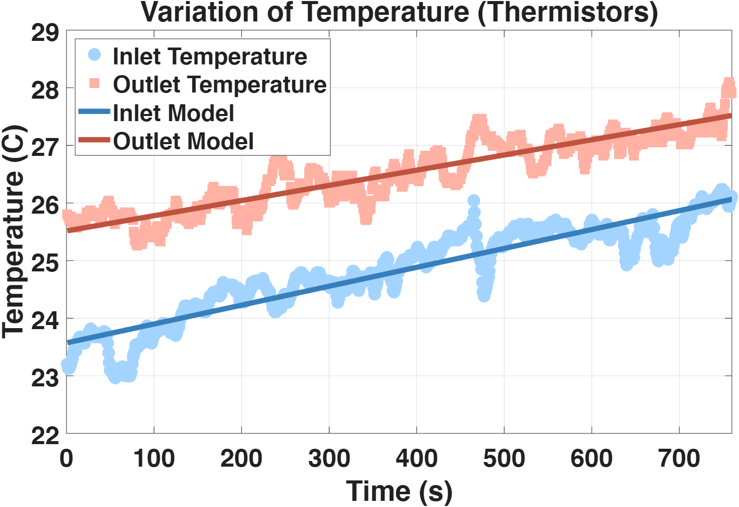
Scatter plot with trendlines showing solar collector inlet temperature rising from 23 to 26 °C and outlet temperature rising from 25.5 to 28 °C over 750 seconds of testing, with model curves tracking the measured data.
datasetSolar collector test — temperature dataInlet and outlet temperature traces from the solar collector prototype test, showing a consistent 2–3 °C differential.
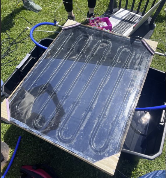
Photograph of the solar collector prototype during outdoor testing: a glass-topped panel with serpentine copper channels on a plywood frame, connected to blue silicone hoses feeding into collection bins, with a laptop logging data.
photoSolar collector prototype — outdoor testThe solar collector prototype during outdoor testing: serpentine copper channels under glass, data-logged in real time.
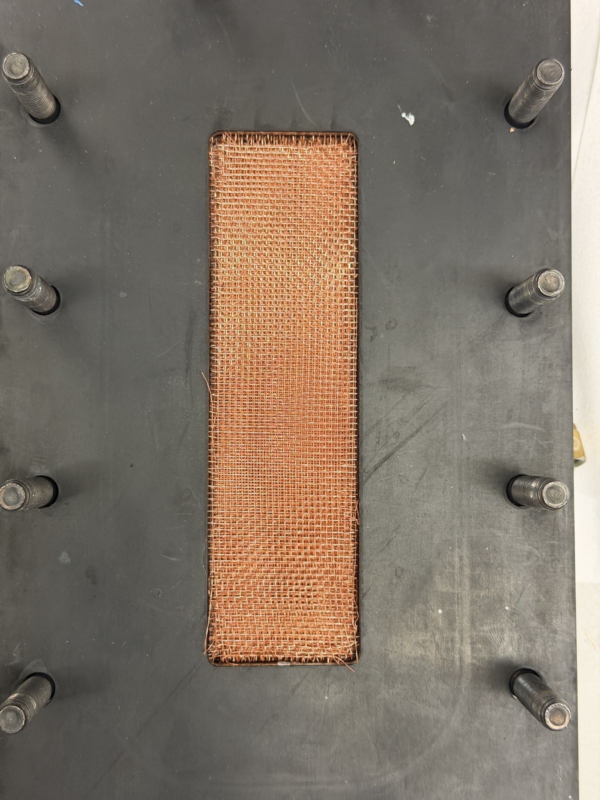
Top-down view of a machined module plate with a copper wire mesh insert set into a rectangular slot, surrounded by threaded mounting studs.
photoBuild — conductive gap copper meshCopper wire mesh set into the module's conductive gap slot, machined into the housing plate that forms the feed-side flow path.
Close-up of a module plate with a rounded rectangular gasket channel, copper mesh, and a row of soldered pin-fin contacts visible through the feed-side opening.
photoBuild — feed-side conductive finsFeed-side opening of the module housing, showing the copper mesh and a row of soldered pin-fin contacts that carry heat across the conductive gap.
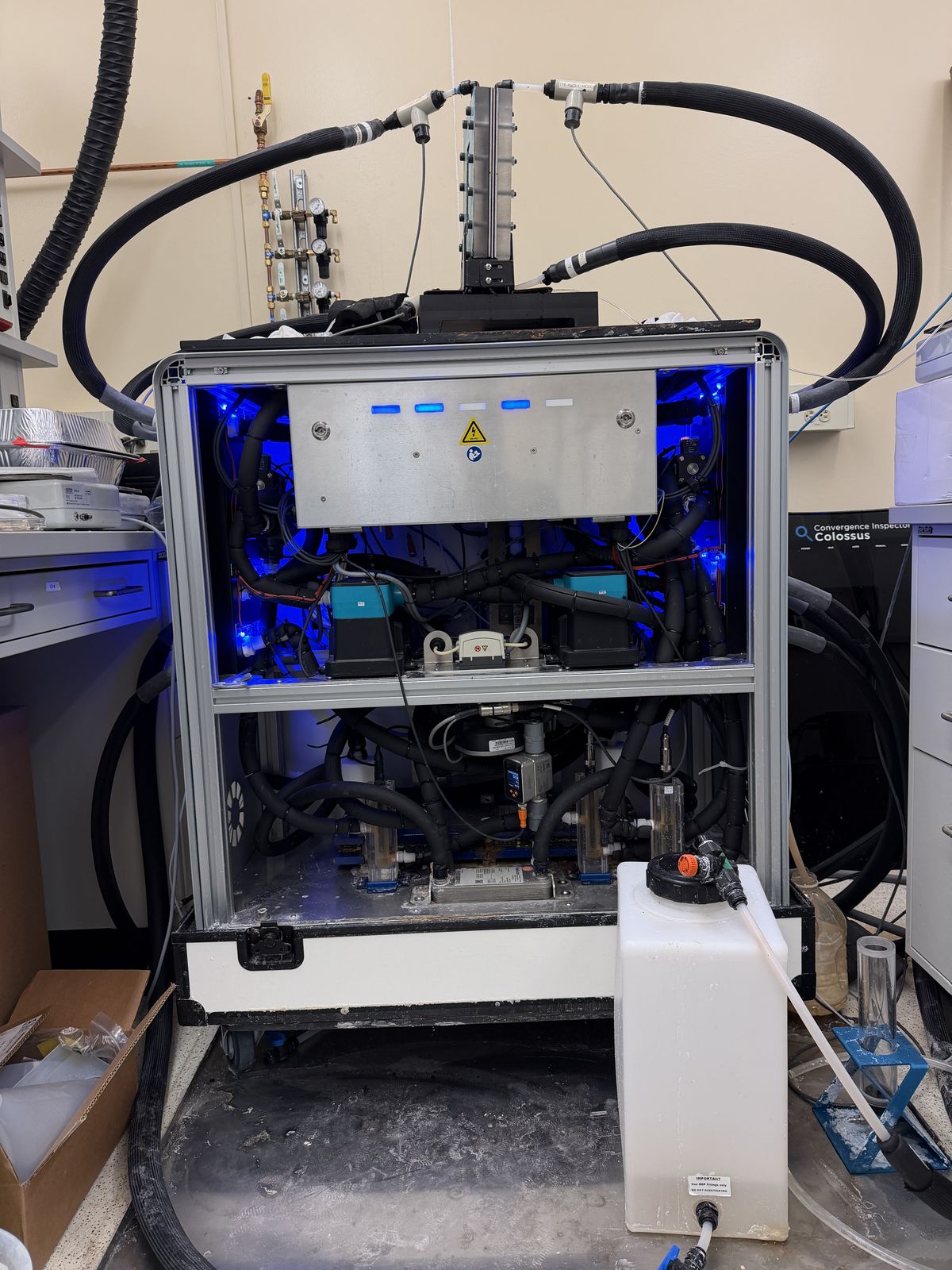
The unlabeled membrane distillation test rig in the Warsinger Lab, showing the aluminum extrusion frame, tubing loops, blue indicator lights, pumps, and feed reservoir.
photoBuild & test — full lab test rigThe complete membrane distillation test rig in the Warsinger Lab: aluminum extrusion frame, feed and cold-water tubing loops, pumps, and reservoir, unlabeled.
Close-up through a Garlock gasket sheet window showing a finned module insert with a row of pin-fin contacts visible inside the housing cavity.
photoBuild — finned module gasket windowFinned module insert viewed through the gasket sheet window, showing the row of pin-fin contacts inside the housing cavity during assembly.
Rotated close-up through a Garlock gasket sheet window showing the same finned module insert and pin-fin contacts inside the housing cavity.
photoBuild — finned module gasket window, alternate angleA second angle of the finned module insert and pin-fin contacts, viewed through the same gasket sheet window.
Overhead view of the module housing plate bolted down with twelve studs, showing a rounded rectangular gasket seal around a membrane window with copper pin contacts, a gloved hand and wrench visible at the edge.
photoBuild — fins and membrane housing, boltedModule housing plate torqued down on twelve studs, with the gasket seal and membrane window visible over the copper pin-fin array.
Black gasket-and-housing plate with twelve threaded studs and a rectangular membrane window showing beads of condensation, held by a technician for assembly.
photoBuild — membrane gasket sandwichThe gasket-and-housing sandwich during module assembly, with condensation visible on the membrane window before the stack is closed and bolted.
Group of middle-school-age students outdoors at a table running a colorimetric water-testing demo, mixing colored solutions in clear cups with test strips.
photoLeading the team — K-12 outreach demoMiddle-school students running a colorimetric water-testing demo outdoors, part of ThermOcean's K-12 outreach on desalination and water quality.
Samarth Rastogi in a suit speaking into a microphone at a wood-paneled podium branded with the Pacific Ocean Energy Trust (POET) logo, audience visible in foreground.
photoLeading the team — MECC quick pitch, PortlandSamarth Rastogi delivering ThermOcean's quick pitch at the DOE Marine Energy Collegiate Competition (MECC), hosted by the Pacific Ocean Energy Trust in Portland, 2026.
Top-down view of the assembled conductive-gap membrane distillation module during a test: a teal Garlock Blue-Gard gasket bolted around a rectangular window that exposes the membrane, with the pin-fin bumps and beads of permeate condensation visible through it.
photoGasket face and membrane window, mid-testThe bolted Garlock gasket and membrane window during a run — pin-fin impressions and permeate beading visible through the membrane.

Further reading